80S-2080F480F5.pdf - 第333页
SIPLACE 80S-20/F4/F5 User M anual 5 Vision Func tions 05/99 Issue from Software Vers ion SR.405.xx 5.6 Test Comp onent Line en gineer 5 - 101 This me nu is us ed to s tore the generated video i mage as a file o n the h a…
5 Vision Functions SIPLACE 80S-20/F4/F5 User Manual
5.6 Test Component 05/99 Issue from Software Version SR.405.xx
5 - 100 Line engineer
Cross:
white: Measured ball candidates which are defined in the package form file.
Crosshairs:
white: Results of position recognition -> x and y angles
Star:
white: Position of the component
Synthetic ball model representation
in pixel resolution on the lefthand edge of the video image
A description will be found in the
Grid-driven mode
section.
5.6.4.5
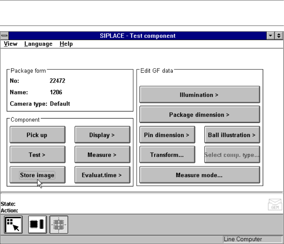
Store image
Option
NOTE
You cannot click on this option until a package form number has been loaded.
Fig. 5.6.22 Test component menu, Store image option
SIPLACE 80S-20/F4/F5 User Manual 5 Vision Functions
05/99 Issue from Software Version SR.405.xx 5.6 Test Component
Line engineer 5 - 101
This menu is used to store the generated video image as a file on the hard disk of the machine controller. The
file name and path are preset to:
C:\TMP\MVSBILD.MVS
For further analysis at Siemens AG, copy the file from the hard disk of the MVS controller onto a diskette and
send it to the AUT 5 Service Department.
5.6.4.6
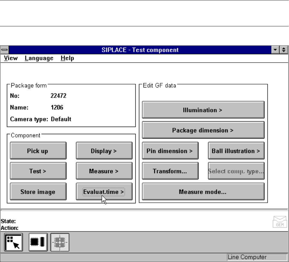
Analysis time
Option
NOTE
You cannot click on this option until a package form number has been loaded.
Fig. 5.6.23
Test component
menu,
Analysis time
option
This option is used to display the analysis time for a selected component. Once you have activated the func-
tion, the following actions are started:
– The measuring procedure is activated.
– The video image appears on the screen
– The analysis time is overlaid.
5 Vision Functions SIPLACE 80S-20/F4/F5 User Manual
5.6 Test Component 05/99 Issue from Software Version SR.405.xx
5 - 102 Line engineer
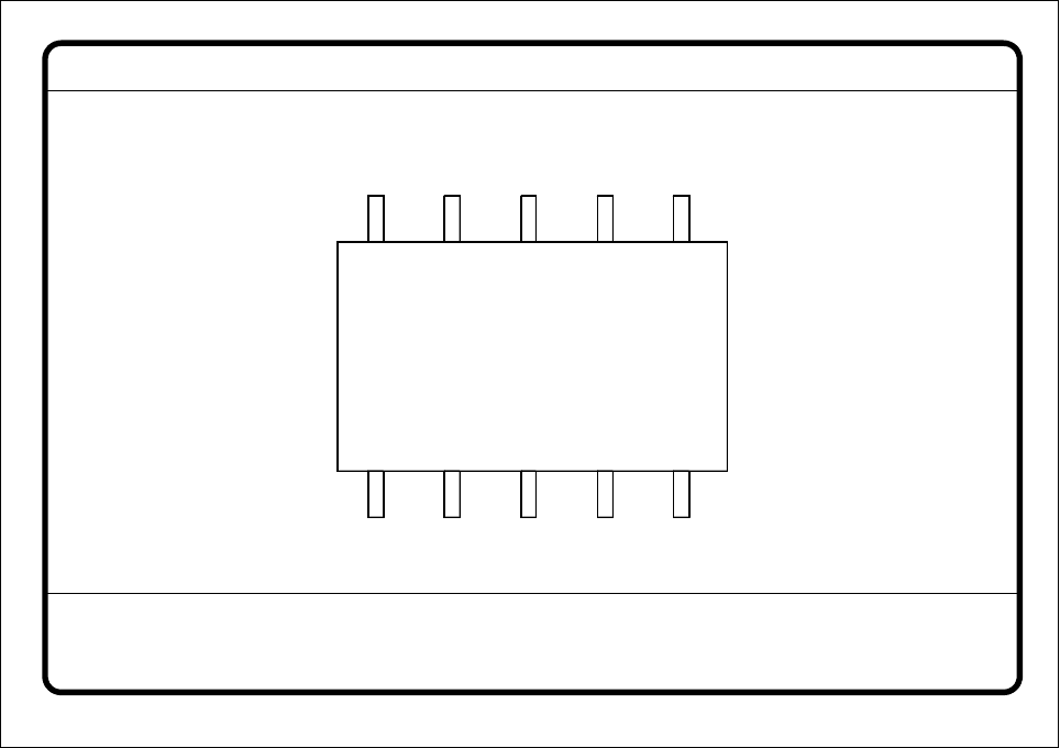
Fig. 5.6.24
Test component
menu,
Analysis time
video image
– Press the RETURN key to start the measurement. Once the measuring procedure has ended, the measur-
ing time in msec is overlaid.
– Press ESC to leave the option. The video image will disappear and the ‘Test component’ menu will appear
once more.
5.6.4.7 Information on the Group of
Edit GF Data
Options
The following options belong to the
Edit GF data
group of options:
– Lighting
– Package dimensions
– Lead dimensions
– Ball illustration
– Transformation table
– Select component type (80F
4
or 80F
5
machines only, see Section 5.10 from Page 5 - 163)
– Measure mode
The GF or package form file is stored in the line computer. Basically it consists of two main parts:
– the geometric package form data and
– the sensor-specific data.
GF No. = 5
Evaluation time
Evaluation time [ms] =
RET: Measure component