80S-2080F480F5.pdf - 第335页
SIPLACE 80S-20/F4/F5 User M anual 5 Vision Func tions 05/99 Issue from Software Vers ion SR.405.xx 5.6 Test Comp onent Line en gineer 5 - 103 The sens or-spec ific part contains – t he meas urement conditio ns for th e c…
5 Vision Functions SIPLACE 80S-20/F4/F5 User Manual
5.6 Test Component 05/99 Issue from Software Version SR.405.xx
5 - 102 Line engineer
Fig. 5.6.24
Test component
menu,
Analysis time
video image
– Press the RETURN key to start the measurement. Once the measuring procedure has ended, the measur-
ing time in msec is overlaid.
– Press ESC to leave the option. The video image will disappear and the ‘Test component’ menu will appear
once more.
5.6.4.7 Information on the Group of
Edit GF Data
Options
The following options belong to the
Edit GF data
group of options:
– Lighting
– Package dimensions
– Lead dimensions
– Ball illustration
– Transformation table
– Select component type (80F
4
or 80F
5
machines only, see Section 5.10 from Page 5 - 163)
– Measure mode
The GF or package form file is stored in the line computer. Basically it consists of two main parts:
– the geometric package form data and
– the sensor-specific data.
GF No. = 5
Evaluation time
Evaluation time [ms] =
RET: Measure component
SIPLACE 80S-20/F4/F5 User Manual 5 Vision Functions
05/99 Issue from Software Version SR.405.xx 5.6 Test Component
Line engineer 5 - 103
The sensor-specific part contains
– the measurement conditions for the component,
– the type of lighting and
– the transformation table data.
NOTE
The buttons of the options of the
Test component
menu will only be active if you have already loaded a pack-
age form.
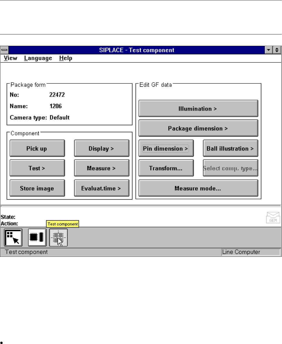
Fig. 5.6.25
Test component
menu, ’Edit GF data’ options
This menu allows you to change
– the lead dimensions,
– the package dimensions,
– the ball imaging parameters,
– the illumination parameters and,
– the transformation table.
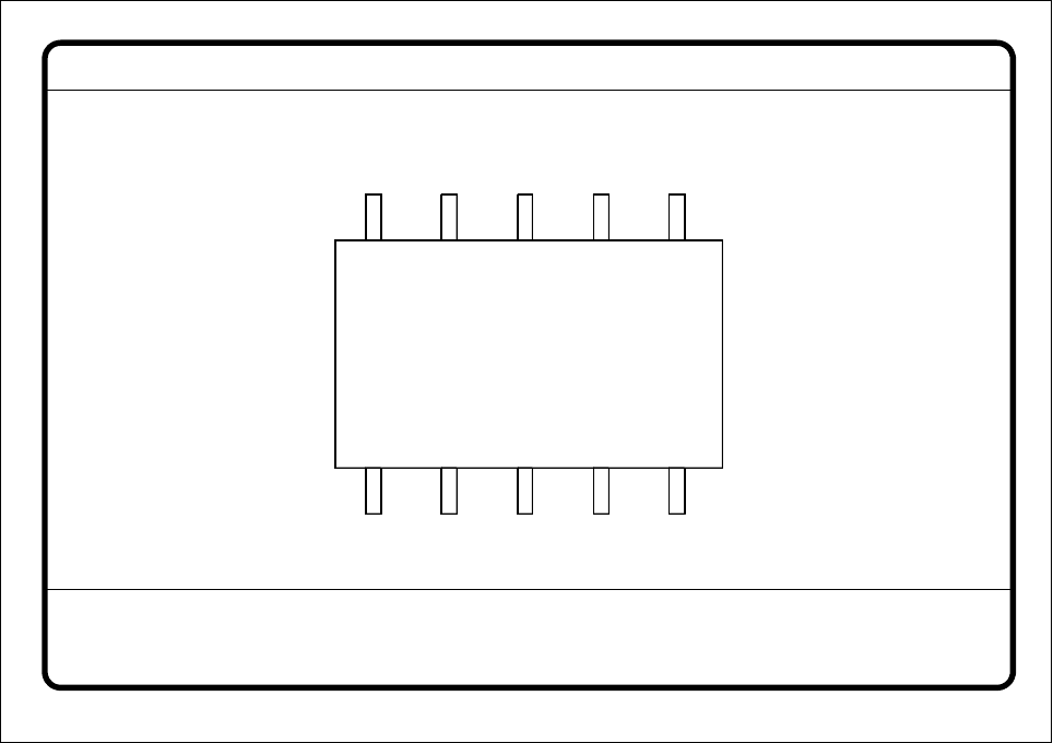
Lead dimension parameters are
– optical lead length in the x and y directions of the component
– optically lead width in the x and y directions of the component

5 Vision Functions SIPLACE 80S-20/F4/F5 User Manual
5.6 Test Component 05/99 Issue from Software Version SR.405.xx
5 - 104 Line engineer
– pitch of the leads in the x and y directions of the component. By pitch is meant the distance from the
center of one lead to the center of the next.
– number of leads in the x and y directions of the component
NOTE
The pitch and number of leads can only be changed in the line computer.
Package dimension parameters are
– the outside dimensions of the component in millimeters in the x and y directions. By outside dimen-
sions is meant the optical dimensions of the component including the lead dimensions.
The geometric dimensions of the leads and component are stored in the GF file in the line computer.
Depending on the geometry of the component and on its illumination by the component camera it is possi-
ble that imaging errors may occur. The image does not reproduce the life-size geometric dimensions but
reduces them. This is what is called imaging reduction. For this reason one refers to the optical dimensions
of the leads and component. Set the component dimensions in a way that they match the visible compo-
nent outline. For each lead dimension and package form the reduction factor is included in the GF file in
the line computer and can be modified with this menu. The reduction factor is entered in the „Real-MA“ file.
As regards defining the position of the origin of the coordinates system and defining regular and irregular
components, please refer to Section 5.3.4.
Ball imaging parameters are
– inner and outer radius type
– inner and outer radius (usually not used)
– contrast
– ball model
Illumination parameters are
– the contrast in the image
– the X plane, flat, middle and steep illumination levels for illuminating the component
(brightness control).
Color representation parameters (5 sections)
– 10 parameter IN values
– 10 parameter OUT values
The parameters are stored in the GF file in the line computer. Upon request the GF file will be sent to the
station computer. Finally it will be converted and transferred to the MVS computer.
If you modify a parameter, it will be entered in the x.SST file. The x.SST file will be converted and loaded into
the MVS computer.