80S-2080F480F5.pdf - 第337页
SIPLACE 80S-20/F4/F5 User M anual 5 Vision Func tions 05/99 Issue from Software Vers ion SR.405.xx 5.6 Test Comp onent Line en gineer 5 - 105 5.6.4. 8 Illumination Option When th is option is sel ected the v ideo ima ge …

5 Vision Functions SIPLACE 80S-20/F4/F5 User Manual
5.6 Test Component 05/99 Issue from Software Version SR.405.xx
5 - 104 Line engineer
– pitch of the leads in the x and y directions of the component. By pitch is meant the distance from the
center of one lead to the center of the next.
– number of leads in the x and y directions of the component
NOTE
The pitch and number of leads can only be changed in the line computer.
Package dimension parameters are
– the outside dimensions of the component in millimeters in the x and y directions. By outside dimen-
sions is meant the optical dimensions of the component including the lead dimensions.
The geometric dimensions of the leads and component are stored in the GF file in the line computer.
Depending on the geometry of the component and on its illumination by the component camera it is possi-
ble that imaging errors may occur. The image does not reproduce the life-size geometric dimensions but
reduces them. This is what is called imaging reduction. For this reason one refers to the optical dimensions
of the leads and component. Set the component dimensions in a way that they match the visible compo-
nent outline. For each lead dimension and package form the reduction factor is included in the GF file in
the line computer and can be modified with this menu. The reduction factor is entered in the „Real-MA“ file.
As regards defining the position of the origin of the coordinates system and defining regular and irregular
components, please refer to Section 5.3.4.
Ball imaging parameters are
– inner and outer radius type
– inner and outer radius (usually not used)
– contrast
– ball model
Illumination parameters are
– the contrast in the image
– the X plane, flat, middle and steep illumination levels for illuminating the component
(brightness control).
Color representation parameters (5 sections)
– 10 parameter IN values
– 10 parameter OUT values
The parameters are stored in the GF file in the line computer. Upon request the GF file will be sent to the
station computer. Finally it will be converted and transferred to the MVS computer.
If you modify a parameter, it will be entered in the x.SST file. The x.SST file will be converted and loaded into
the MVS computer.
SIPLACE 80S-20/F4/F5 User Manual 5 Vision Functions
05/99 Issue from Software Version SR.405.xx 5.6 Test Component
Line engineer 5 - 105
5.6.4.8
Illumination
Option
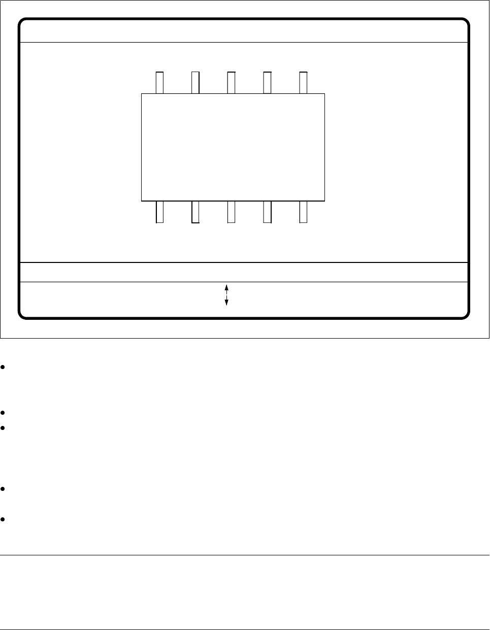
When this option is selected the video image for checking and setting illumination will appear.
Fig. 5.6.26
Test component
menu,
Illumination
video image
You can use the arrow keys to increase or decrease the brightness of the rows of LEDs in the component
camera system which illuminate the component. The brightness can be set within a range of 256 steps
with 255 being the maximum value.
Use the spacebar to toggle the step size for changing the brightness from 1 to 10 µm and back.
Use the tab key to move between the four illumination levels: steep (top row of LEDs), medium (second
row of LEDs), flat (third row of LEDs) and X plane camera lighting (bottom row of LEDs). The X plane illu-
mination level is used to optically center flip-chip components on the 6-nozzle revolver head with the illumi-
nation system for flip-chips, bare dies and standard components.
Press the
Return
key to execute the individual measurement steps which are included in the measure-
ment conditions.
With Esc you can quit the option. You will then be returned to the Test component menu.
NOTE
Section 5.7.6 ’Setting the Components Illumination at the 12x Revolver Head Camera’, Page 134, and Sec-
tion 5.7.7 ’Setting the Components Illumination at the IC Head Camera’, Page 141, contain instructions for
selecting the illumination parameters.
GF No. = 5Illumination
RET: Test component
Illuminat. = X plane/flat/middle/steep Field step =
Blank: step width
Tab: Illumination
Brightness = 0 ... 255
: Brightness up
: Brightness down
5 Vision Functions SIPLACE 80S-20/F4/F5 User Manual
5.6 Test Component 05/99 Issue from Software Version SR.405.xx
5 - 106 Line engineer
5.6.4.9
Package Dimension
Option
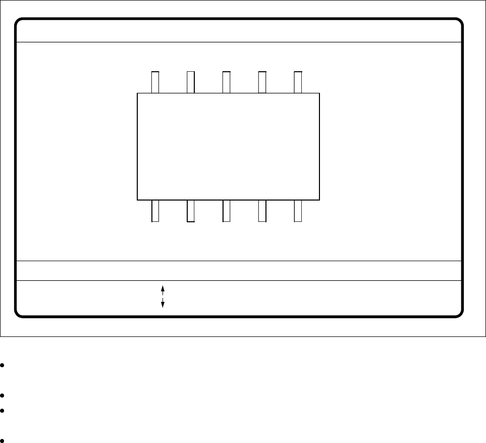
Here you have the possibility of changing the optical package width and length should the imaging reduction
effect be too marked. This effect occurs mainly with cylindrical components, with PLCCs, BGAs, and µBGAs.
Fig. 5.6.27
Test component
menu,
Package dimension
video image
With the arrow keys you can change the length and width of the component. The current geometric data
will be displayed (see desctiption on page 5 - 104).
Use the spacebar to select different sides of the component.
With the
Return
key you can trigger the individual measurement steps which are specified in the measure-
ment conditions.
Press
Esc
to quit the option.
GF No. = 5
: larger
: smaller
RET: Test component
Blank: Pack. side
Pack. side = opt. l.[mm] = ... opt. w.[mm] = ...
Pin dimension