80S-2080F480F5.pdf - 第357页
SIPLACE 80S-20/F4/F5 User M anual 5 Vision Func tions 05/99 Issue from Software Vers ion SR.405.xx 5.6 Test Comp onent Line en gineer 5 - 125 PLEASE NOTE: Measur ement mod e grid can be spe eded up, if measu rement mo de…
5 Vision Functions SIPLACE 80S-20/F4/F5 User Manual
5.6 Test Component 05/99 Issue from Software Version SR.405.xx
5 - 124 Line engineer
– measuring the tips via the inner tips of the leads, for bases, for example
– center of the lead, center measurement, for PLCC, SOJ, for example
– measuring the tips via the outer tips of the leads, for QFP, SOT, SO, for example
Windows
–
Separately for each lead
Here you define the window in the primary direction (dark blue) and secondary direction (light blue) for
measuring each standard lead for irregular components and special components.
–
Combined window
Used to define a common window for all the leads. This applies to four-sided, symmetrical components
only.
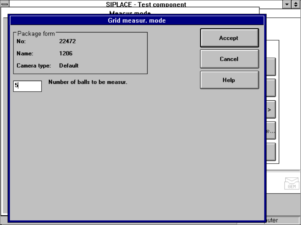
5.6.4.20 ‘Grid’ measuring mode
Click on the ‘Setting’ field in the ‘Grid’ measuring mode to call up the
Grid measuring mode
menu.
Fig. 5.6.41
Measuring mode
option,
Grid measuring mode
menu
In this menu, enter the number of balls to be measured at each corner:
– 3 for single measurement
– 5 for multiple measurement
SIPLACE 80S-20/F4/F5 User Manual 5 Vision Functions
05/99 Issue from Software Version SR.405.xx 5.6 Test Component
Line engineer 5 - 125
PLEASE NOTE:
Measurement mode grid can be speeded up, if measurement mode Size is carried out beforehand.
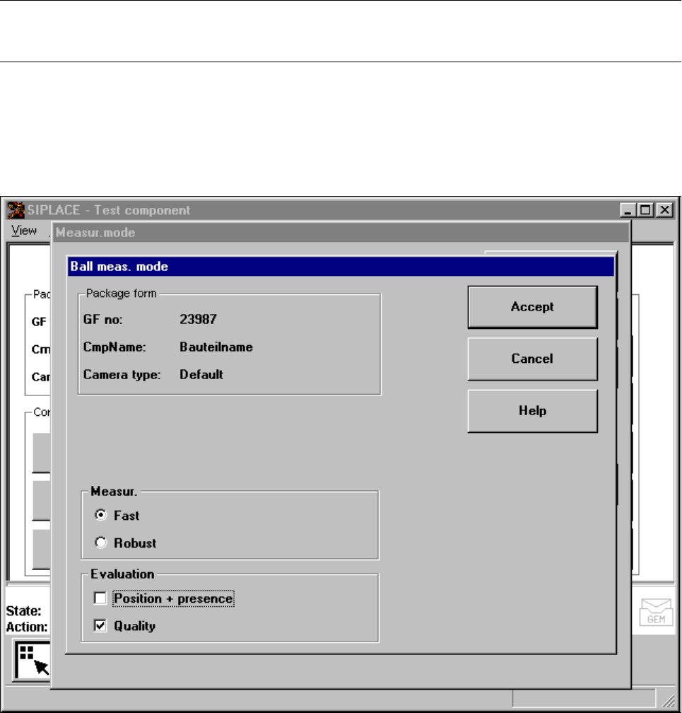
5.6.4.21 ’Ball’ measuring mode
Click on the ’Settings’ button in ’Ball’ measuring mode to call up the ’’Ball measuring mode“ menu.
Fig. 5.6.42 ’Measuring mode’ option, ’’Ball measuring mode“ menu
This menu can be used to
– select the measuring methods listed under ’Measurement’ and
– evaluate the position and presence of balls and carry out a quality analysis.
Measurement
You can choose between the following measuring methods:
– the profile method for fast analysis or
– the filter method for a more robust measuring method, although this will take longer.
The ’fast’ measuring method is generally sufficient. However, for critical components we recommend the
’robust’ measuring method, if the quality is insufficient, for example if the quality factor is less than 50.
5 Vision Functions SIPLACE 80S-20/F4/F5 User Manual
5.6 Test Component 05/99 Issue from Software Version SR.405.xx
5 - 126 Line engineer
Analysis
This is used to analyze the position of the balls and to determine whether they are present. It can also be used
to determine the quality of the measurement. The quality of the measurement should generally be better than
50.
If you are inserting BGAs, µBGAs, or flip-chips with high reproducibility, i.e. if there is very little difference bet-
ween the optical parameters of the flip-chips, we recommend the following settings to guarantee fast insertion:
– Switch off the determination of position / presence for components with large balls and spacing. The posi-
tion of the components has already been adequately determined using the grid measurement of 3 balls per
corner, and the ball presence analysis is unnecessary.
– Do not activate determination of the quality of the measurement unless you want to detect handling or pro-
duction errors.
Determination of the position is always necessary if the individual ball positions differ greatly from the grid
structure, i.e. if the individual ball positions are fairly scattered about the desired position.