80S-2080F480F5.pdf - 第36页
0 Introduction SIPLACE 80S-20/F4 /F5 User Manual 0.4 Overall View of Assemblies 05/99 Issue from Software Version SR.405.xx 0 - 32 0.4.10 Overall V iew of PCB T rans port Fig. 0.4.10 Overall view of PCB transport - Key t…
SIPLACE 80S-20/F4/F5 User Manual 0 Introduction
05/99 Issue from Software Version SR.405.xx 0.4 Overall View of Assemblies
0 - 31
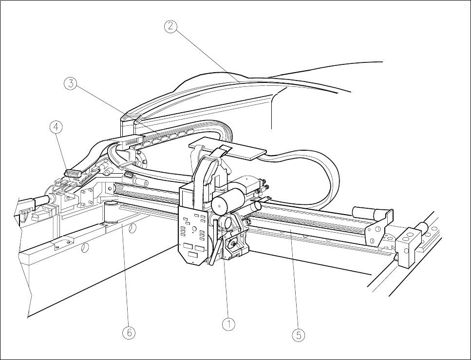
0.4.9 Overall View of the Gantry
Fig. 0.4.9 Overall view of the gantry
- Key to Fig. 0.4.9
1 Revolver head 2 Protective cover
3 Drag cable 4 Gantry axes conversion board
5 X axis 6 Y axis
0 Introduction SIPLACE 80S-20/F4/F5 User Manual
0.4 Overall View of Assemblies 05/99 Issue from Software Version SR.405.xx
0 - 32
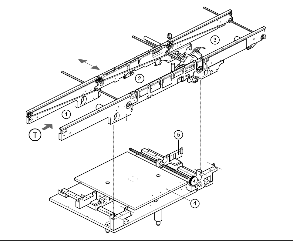
0.4.10 Overall View of PCB Transport
Fig. 0.4.10 Overall view of PCB transport
- Key to Fig. 0.4.10
1 Input conveyor 2 Center conveyor
3 Output conveyor 4 Lifting table
5 Width adjustment T Direction of PCB transport
r
SIPLACE 80S-20/F4/F5 User Manual
05/99 Issue from Software Version SR.405.xx
1 - I
Contents
Page
1 Operational Safety
1.1 Information on safety. . . . . . . . . . . . . . . . . . . . . . . . . . . . . . . . . . . . . . . . . . . . . . . . . . . . . .1 - 3
1.1.1 Convention for the use of danger symbols. . . . . . . . . . . . . . . . . . . . . . . . . . . . . . . . . . . . . . . 1 - 3
1.1.2 Qualified personnel. . . . . . . . . . . . . . . . . . . . . . . . . . . . . . . . . . . . . . . . . . . . . . . . . . . . . . . . . 1 - 3
1.1.3 Use as prescribed. . . . . . . . . . . . . . . . . . . . . . . . . . . . . . . . . . . . . . . . . . . . . . . . . . . . . . . . . . 1 - 4
1.1.4 Important notes on operational safety . . . . . . . . . . . . . . . . . . . . . . . . . . . . . . . . . . . . . . . . . . 1 - 4
1.1.5 Warning signs on the placement system . . . . . . . . . . . . . . . . . . . . . . . . . . . . . . . . . . . . . . . . 1 - 6
1.1.6 Additional warning signs for the NAFTA region . . . . . . . . . . . . . . . . . . . . . . . . . . . . . . . . . . 1 - 12
1.1.7 Safety instructions for component vision systems on
80F4 or 80F5 automatic placement systems . . . . . . . . . . . . . . . . . . . . . . . . . . . . . . . . . . . .1 - 14
1.1.8 Safety instructions for the coplanarity laser module. . . . . . . . . . . . . . . . . . . . . . . . . . . . . . . 1 - 16
1.1.9 Safety instructions for the PCB barcode reader (option) . . . . . . . . . . . . . . . . . . . . . . . . . . . 1 - 18
1.1.10 Safety instructions for changing the component table . . . . . . . . . . . . . . . . . . . . . . . . . . . . . 1 - 19
1.1.11 Safety instructions for opening the protective covers. . . . . . . . . . . . . . . . . . . . . . . . . . . . . .1 - 20
1.2 Safety equipment . . . . . . . . . . . . . . . . . . . . . . . . . . . . . . . . . . . . . . . . . . . . . . . . . . . . . . . . 1 - 23
1.2.1 Protective covers . . . . . . . . . . . . . . . . . . . . . . . . . . . . . . . . . . . . . . . . . . . . . . . . . . . . . . . . . 1 - 23
1.2.1.1 General. . . . . . . . . . . . . . . . . . . . . . . . . . . . . . . . . . . . . . . . . . . . . . . . . . . . . . . . . . . . . . . . . 1 - 24
1.2.2 Guard on the input / output conveyor. . . . . . . . . . . . . . . . . . . . . . . . . . . . . . . . . . . . . . . . . . 1 - 25
1.2.3 Emergency stop button, protective cover switch and key switch . . . . . . . . . . . . . . . . . . . . . 1 - 26
1.2.3.1 Functional description. . . . . . . . . . . . . . . . . . . . . . . . . . . . . . . . . . . . . . . . . . . . . . . . . . . . . .1 - 27
1.2.3.2 Status messages and the action required . . . . . . . . . . . . . . . . . . . . . . . . . . . . . . . . . . . . . . 1 - 27
1.2.4 Safety circuits. . . . . . . . . . . . . . . . . . . . . . . . . . . . . . . . . . . . . . . . . . . . . . . . . . . . . . . . . . . . 1 - 28
1.2.5 Guard on the component table locations . . . . . . . . . . . . . . . . . . . . . . . . . . . . . . . . . . . . . . . 1 - 30
1.3 Residual voltages in the servo unit and discharge
times when placement system is switched off . . . . . . . . . . . . . . . . . . . . . . . . . . . . . . . . 1 - 31
1.3.1 Operating voltages, residual voltages and discharge times after
pressing the emergency stop button . . . . . . . . . . . . . . . . . . . . . . . . . . . . . . . . . . . . . . . . . . 1 - 32
1.3.2 Residual voltages and discharge times after switching off at the main switch. . . . . . . . . . .1 - 32
1.4 Disabling the compressed air supply and discharging the pressure . . . . . . . . . . . . . . 1 - 33
1.5 Energy state of automatic placement systems after switching off at the main switch1 - 35
1.5.1 Placement system switched off at the main switch, but still connected to the mains. . . . . . 1 - 36
1.5.2 Placement system switched off at the main switch and disconnected from the mains . . . .1 - 36
1.5.3 Compressed air conditions in the automatic placement system
after switching off at the main switch . . . . . . . . . . . . . . . . . . . . . . . . . . . . . . . . . . . . . . . . . . 1 - 36
1.6 Lock out and tag out procedure . . . . . . . . . . . . . . . . . . . . . . . . . . . . . . . . . . . . . . . . . . . . 1 - 37
1.6.1 Purpose and scope. . . . . . . . . . . . . . . . . . . . . . . . . . . . . . . . . . . . . . . . . . . . . . . . . . . . . . . . 1 - 37
1.6.2 Description . . . . . . . . . . . . . . . . . . . . . . . . . . . . . . . . . . . . . . . . . . . . . . . . . . . . . . . . . . . . . . 1 - 37