80S-2080F480F5.pdf - 第368页
5 Vision Functions SIP LACE 80S-20/F4/F5 Us er Manual 5.7 Guidelines for Describi ng Package Forms 05/99 Issue from Software Version SR.405.xx 5 - 136 Line en gineer 5.7.6.2 Pseudo color representation The pseudo c olor …

SIPLACE 80S-20/F4/F5 User Manual 5 Vision Functions
05/99 Issue from Software Version SR.405.xx 5.7 Guidelines for Describing Package Forms
Line engineer 5 - 135
Flat illumination level
The flat illumination level is used for illuminating BGAs, µBGAs, flip-chips, J-lead components (PLCC), Melfs
and components with convex-type leads. It tends to emphasize body and lead edges. It is, however, less suit-
able for displaying bright component bodies and ceramic components.
Middle illumination level
The middle illumination level can be used universally with a wide range of components. With bright compo-
nent bodies, ceramic components, µBGAs and flip-chips it should, however, only be used at lower intensity
levels.
Steep illumination level
The main application for the steep illumination level is for reflective leads, ceramic components and bright
component bodies. It is less suitable for reflective component bodies, flip-chips or µBGAs.
NOTE
Most components will require a combination of these three illumination levels to achieve optimum illumination.
Using
one
illumination level will only be successful in exceptional cases.
5 Vision Functions SIPLACE 80S-20/F4/F5 User Manual
5.7 Guidelines for Describing Package Forms 05/99 Issue from Software Version SR.405.xx
5 - 136 Line engineer
5.7.6.2 Pseudo color representation
The pseudo color representation provides a powerful and objective assessment of the illumination, by repre-
senting a brightness value in a color.
A contrast of at least 4 color scales between the lead and body is required for a measurement. In the ‘Illumina-
tion’ menu of the package form manipulator, components are displayed in the pseudo color representation on
the station computer monitor.
5.7.6.3 Settings for Illuminating Standard Components
The standard range of components includes chips (0402 to 2220), tantalum capacitors, Melf components,
PLCCs, QFPs, SOs, SOJs, TSOPs, ICs, power components, flip-chips, µBGAs and BGAs.
For the components which are listed below the GF interpreter in the station computer uses the default illumi-
nation parameters listed in Fig. 5.7.7:
– Chips (0402 to 2220)
– Tantalum capacitors (component bodies, non-reflective)
– Melf
– PLCC, QFP, SO, SOJ, TSOP, ICs, power ICs
– Flip-chips, µBGAs, BGAs (not ceramic BGAs)
As a rule you will not need to change the illumination parameters for the standard components. For all other
components you will need to determine the illumination values and test them (see Section 5.7.6.4, Page 5 -
137).
Color scale Brightness
white light
yellow
orange
red
brown
green
light blue
blue
violet
black dark
Tab. 5.7.3 Conversion table for the pseudo color representation at the 12x revolver head
SIPLACE 80S-20/F4/F5 User Manual 5 Vision Functions
05/99 Issue from Software Version SR.405.xx 5.7 Guidelines for Describing Package Forms
Line engineer 5 - 137
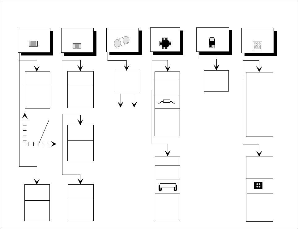
Fig. 5.7.7 Illumination parameters for standard components at the 12x revolver head camera
5.7.6.4 Settings for Illuminating Other Components
Fig. 5.7.8 presents a list of the illumination settings for other components.
flat: 255
middle: 90
steep: 60
Diagram for adjusting the illumination of standard components
Chip
IC
Power IC
Melf BGA, µBGA
flip-chip
Tantalum
capacitor
BGA,
µBGA,
flip-chip
0805 and
larger
0402,
0603
Light
General
flat: 120
middle: 40
steep: 170
Reflective
body
flat: 120
middle: 100
steep: 120
flat: 70
middle: 60
steep: 150
Gullwing
SO, SOT,
TSOP
QFP,
flat: 170
middle: 50
steep: 120
flat: 0
middle: 10
steep: 170
flat: 255
middle: 120
steep: 10
flat: 170
middle: 60
steep: 120
J-Lead
PLCC
flat: 80
middle: 40
steep: 120
Ceramic
BGA
flat: 0
middle: 50
steep: 255
flat: 255
middle: 20
steep: 0
Illumination
level
Brightness
150
255
Contrast
graduation