80S-2080F480F5.pdf - 第375页
SIPLACE 80S-20/F4/F5 User M anual 5 Vision Func tions 05/99 Issue from Software Version SR.405.xx 5.7 Guidelines for D escribing Package F orms Line en gineer 5 - 143 Fig. 5.7.9 Illumination p arameters for standard comp…
5 Vision Functions SIPLACE 80S-20/F4/F5 User Manual
5.7 Guidelines for Describing Package Forms 05/99 Issue from Software Version SR.405.xx
5 - 142 Line engineer
5.7.7.2 Pseudo color representation
The pseudo color representation provides a powerful and objective assessment of the illumination, by repre-
senting a brightness value in a color.
A contrast of at least 4 color scales between the lead and body is required for a measurement. In the ‘Illumina-
tion’ menu of the package form manipulator, components are displayed in the pseudo color representation on
the station computer monitor.
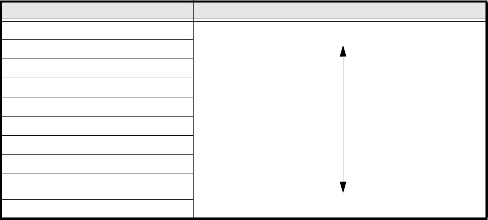
5.7.7.3 Setting values for the illumination of standard components
The range of standard components includes tantalum capacitors, PLCCs, QFPs, SOs, SOJs, TSOPs, ICs,
power components and BGAs.
For the components listed below, the package form interpreter in the station computer uses the preset illumi-
nation parameters listed in Fig. 5.7.9:
– tantalum capacitors (component body, not mirrored)
– PLCC, QFP, SO, SOJ, TSOP, ICs, power ICs
– BGAs (not for ceramic BGAs)
As a rule you will not need to change the illumination parameters for the standard components. For all other
components you will need to determine the illumination values and test them (see Section 5.7.7.4, Page 5 -
143).
Color scale Brightness
white light
yellow
orange
red
brown
green
light blue
blue
violet
black dark
Tab. 5.7.4 Conversion table for the pseudo color representation at the IC head

SIPLACE 80S-20/F4/F5 User Manual 5 Vision Functions
05/99 Issue from Software Version SR.405.xx 5.7 Guidelines for Describing Package Forms
Line engineer 5 - 143
Fig. 5.7.9 Illumination parameters for standard components at the IC head camera.
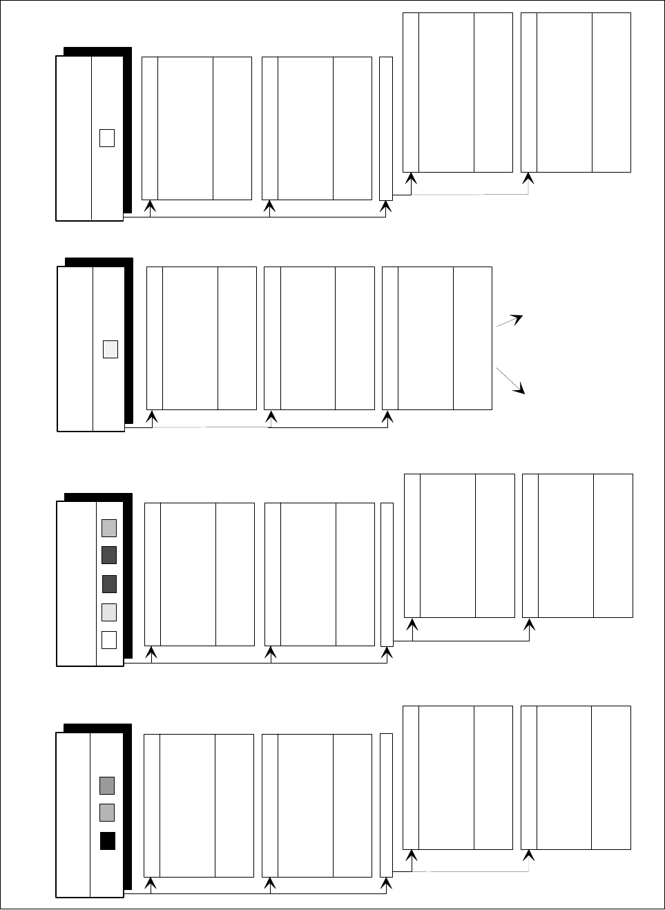
5.7.7.4 Settings for Illuminating Other Components
Fig. 5.7.10 presents a list of the illumination settings for other components.
Diagram for adjusting the illumination of standard components
IC
Power IC
BGA
Tantalum
capacitor
BGA
General
flat: 120
middle: 60
steep: 10
Reflective
body
Gullwing
SO, SOT,
TSOP
QFP,
flat: 90
middle: 40
steep: 10
flat: 255
middle: 90
steep: 0
flat: 120
middle: 50
steep: 10
J-Lead
PLCC
flat: 200
middle: 30
steep: 5
Ceramic
BGA
flat: 0
middle: 0-10
steep:80-100
flat: 255
middle: 30
steep: 0
Illumination
level
Brightness
5 Vision Functions SIPLACE 80S-20/F4/F5 User Manual
5.7 Guidelines for Describing Package Forms 05/99 Issue from Software Version SR.405.xx
5 - 144 Line engineer
Fig. 5.7.10 Illumination parameters for other components at the IC head camera
A
dju
sting the illumination of other com
ponents
L
ig
h
t an
d
d
u
ll b
o
d
y
( w
hite
, yellow
, red, brow
n, g
rey,
m
etallic dull )
C
eram
ic b
o
d
y
D
ark a
n
d
d
u
ll b
o
d
y
( black, blue,
green )
R
eflectiv
e b
o
d
y
(independ
ently of color and m
ate
rial)
D
u
ll le
ads
fla
t: 100
m
iddle: 30
stee
p
: 4
0
V
isu
al sepa
ra
tion
b
etw
een
lea
ds
an
d bod
y is not p
ossible.
Illu
m
in
ate bod
y a
nd
lea
ds eq
ually.
M
ea
sure ou
tline.
S
h
iny lea
d
s
C
le
ar sepa
ra
tion
b
etw
ee
n le
ads
and
b
ody.
D
u
ll le
ads
fla
t: 255
m
iddle: 90
stee
p: 0
S
hiny lea
ds
1. Illum
ina
te
bo
dy an
d le
ads e
qua
lly.
M
easure
o
utlin
e.
2. T
rick: U
se
flat a
nd m
iddle leve
ls
to
brin
g le
ads im
ag
e to
sa
tura
tion
.
M
easure
.
C
le
ar sepa
ra
tion
betw
ee
n
le
ads
a
nd
b
ody.
fo
r va
riant 2:
flat: 1
60
m
id
dle: 6
0
steep
: 0
C
le
ar
sepa
ra
tion
betw
ee
n le
ads
and
b
ody.
C
lea
r sep
aratio
n
be
tw
e
en lea
ds
an
d bod
y.
J-L
ead ( P
LC
C
), convex-typ
e leads
G
ullw
ing
le
a
ds
( S
O
, Q
F
P
)
D
u
ll le
ads
S
hiny lea
ds
C
lea
r sep
arat
io
n
be
tw
e
en lea
ds
an
d bod
y.
C
le
ar sepa
ration
betw
ee
n le
ads
and
b
ody.
J-Lead ( P
LC
C
), co
nvex-type leads
G
ullw
in
g le
ads
( S
O
, Q
F
P
)
fl
a
t: 90
m
id
dle: 40
stee
p
: 10
fl
at: 2
00
m
id
dle: 3
0
steep
: 5
C
le
ar sepa
ra
tio
n
betw
ee
n le
ad
s
and
b
ody.
C
le
ar sepa
ration
betw
ee
n le
ads
and
b
ody.
O
the
r
lead
shap
es
D
ull
le
ads
V
isual se
paratio
n
betw
ee
n lead
s
and
b
ody is no
t g
e
nerally possible.
S
hiny lea
ds
Le
ads:
O
u
tline:
M
e
asu
ring
m
e
th
od:
V
is
ua
l se
paration betw
e
en
lead
s
an
d
b
ody is no
t po
ssible.
Illum
inate
bo
dy an
d le
ads e
qua
lly
.
M
e
asure
o
utlin
e.
V
isual se
paratio
n betw
ee
n lead
s
and
b
ody is no
t po
ssible. M
e
asure
outli
n
e or lea
d tips. Le
ads a
re
outside
the
b
ody.
J-Lead ( P
LC
C
), conve
x-type leads
G
ullw
in
g le
ads
( S
O
, Q
F
P
)
O
th
er lea
d s
ha
pes
C
on
vex
-typ
e le
ads
O
th
er lea
d sha
pes
V
isua
l se
paration betw
e
en lead
s
and
b
ody is no
t g
e
nerally possible.
Illum
inate bo
dy an
d le
ad
s e
qua
lly.
M
easure
o
utlin
e.
Illu
m
in
atio
n
le
vel
B
rig
h
tn
ess
flat: 12
0 -
14
0
m
idd
le
: 40
- 60
ste
ep: 0
- 10
flat: 9
0
m
idd
le
: 90
ste
ep: 5 -
10
fl
at: 9
0
m
id
dle: 4
0
steep
: 10
fl
a
t: 200
m
id
dle: 30
stee
p
: 5
V
isual se
paratio
n betw
ee
n
lead
s
and
b
ody is no
t ge
n
erally possible.
Le
ads:
O
u
tline:
M
e
as
u
ring
m
e
th
od:
fla
t: 1
20
m
id
dle: 4
0
stee
p: 10
- 20
fla
t: 1
20
m
id
dle: 40
stee
p:
0
- 10
fla
t: 0
m
iddle:
0
stee
p: 1
0 - 20
fla
t: 0
m
iddle: 0
stee
p: 2
0 - 40
fla
t: 0
m
iddle: 0
stee
p
: 2
5
fla
t: 100
m
iddle: 30
stee
p: 4
0
flat: 1
60
m
id
dle: 6
0
steep
: 0
flat:
15
0 - 25
5
m
idd
le
:
60 - 1
20
ste
ep:
0