80S-2080F480F5.pdf - 第386页
5 Vision Functions SIP LACE 80S-20/F4/F5 Us er Manual 5.7 Guidelines for Describi ng Package Forms 05/99 Issue from Software Version SR.405.xx 5 - 154 Line en gineer 5.7.9. 4 T esting Ill umination S ettings Y ou can set…
SIPLACE 80S-20/F4/F5 User Manual 5 Vision Functions
05/99 Issue from Software Version SR.405.xx 5.7 Guidelines for Describing Package Forms
Line engineer 5 - 153
.
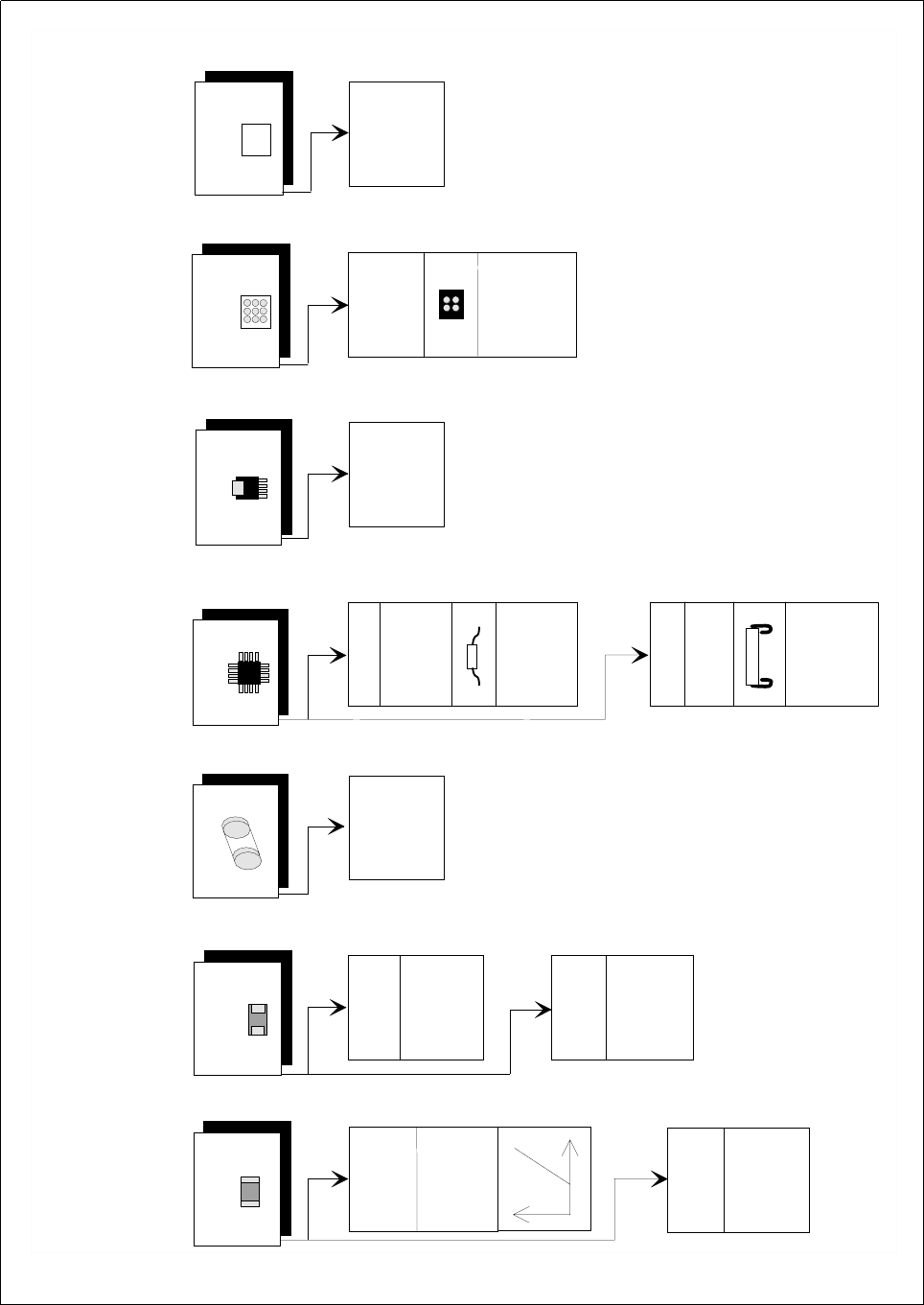
Fig. 5.7.12 Illumination Values for standard components at the 6x revolver head camera (DCA option) on the 80 F
5
placement
machine
A
d
justing the illum
ination o
f standard com
ponents
C
hip
IC
P
ow
er IC
M
elf
B
G
A
, µ
B
G
A
flip-chip
T
antalum
cap
acitor
B
G
A
,
µ
B
G
A
,
flip
-chip
0805 and
larger
020
1,
0402
,
0603
G
eneral
R
eflective
body
X
plane: 50
flat:
50
m
iddle: 50
steep:
50
G
ullw
ing
S
O
, S
O
T
,
T
S
O
P
Q
F
P
,
J-Lead
P
LC
C
255
1
50
X
plane
: 50
flat: 50
m
iddle: 50
steep: 50
X
plane
: 0
flat: 50
m
iddle:
80
steep
: 100
X
pla
ne
: 2
30
flat:
230
m
iddle: 20
steep: 20
X
plane
: 200
flat:
100
m
iddle:
40
steep: 40
X
plan
e
: 0
flat:
80
m
iddle: 50
steep: 50
X
p
lane
:
0
flat: 0
m
iddle: 100
steep:
20
X
pla
ne
: 15
0
flat: 30
m
iddle: 0
steep:
0
B
a
re D
ie
X
plane
: 0
flat:
80
m
iddle:
50
s
teep: 50
X
plane
: 0
flat:
0
m
iddle:
50
s
teep: 110

5 Vision Functions SIPLACE 80S-20/F4/F5 User Manual
5.7 Guidelines for Describing Package Forms 05/99 Issue from Software Version SR.405.xx
5 - 154 Line engineer
5.7.9.4 Testing Illumination Settings
You can set the illumination parameters by calling the ’Illumination’ option (see Section 5.6.4.8, Page 5 - 105).
Using the 'Measure Component Option' you can then measure the component and check your settings with
the aid of the measurement results.
Proceed as follows to test your illumination setting:
Using the illumination values suggested in Fig. 5.7.12 carry out measurement. Measurement should run
through successfully.
For each level reduce the set brightness level by 50 %.
Measurement should run through successfully.
For each level raise the set brightness level by 50 %.
Measurement should run through successfully.
If you are not successful with the above procedure, proceed as follows:
Starting with the suggested illumination value, increase the brightness of each individual illumination level
for as long as measurement is still successful.
Find this upper limit value for each individual illumination level in turn.
Starting with the suggested illumination value, decrease the brightness of each individual illumination level
for as long as measurement is still successful. Find this lower limit value for each individual illumination
level in turn.
Determine the average value of the upper and lower limit values. This will be the optimum illumination
value.
Example of an illumination test:
– Settings from the diagram:
X plane: 200
flat: 100
middle: 40
steep: 40
– Measure the component. Measurement is successful.
– Reduce setting values by 50%.
X plane: 100
flat: 50
middle: 20
steep: 20
– Increase setting values by 50%.
X plane: 255
flat: 150
middle: 60
steep: 60
– Measure the component. Measurement is successful.

SIPLACE 80S-20/F4/F5 User Manual 5 Vision Functions
05/99 Issue from Software Version SR.405.xx 5.7 Guidelines for Describing Package Forms
Line engineer 5 - 155
– Reset the settings to the suggested values:
X plane: 200
flat: 100
middle: 40
steep: 40
¬ optimum setting
NOTE
With respect to 0402 components, avoid the nozzle being displayed during imaging. If this seems likely,
remove the component from the nozzle and use the ’Illumination Option’ on Page 105 to see whether the noz-
zle did appear in the image.
5.7.9.5 General Information on Setting Illumination Values
– As a rule it is better to overilluminate the component than to underilluminate it. A saturated image is prefer-
able to a low-contrast image.
– Optimum illumination is attained when only the leads are imaged and the component body is not shown.
– If you cannot clearly separate the image of the component body from the leads, we recommend to illumi-
nate body and leads equally and then to measure the outline.