80S-2080F480F5.pdf - 第400页
5 Vision Functions SIP LACE 80S-20/F4/F5 Us er Manual 5.11 Coplanarity Laser Module (SIPLACE 80F4 or 80F5 only) 05/99 Issue from Software Version SR.405.xx 5 - 168 Line en gineer 5.1 1.2 T echnical Dat a Components: Ca n…
SIPLACE 80S-20/F4/F5 User Manual 5 Vision Functions
05/99 Issue from Software Version SR.405.xx 5.11 Coplanarity Laser Module (SIPLACE 80F4 or 80F5 only)
Line engineer 5 - 167
5.11 Coplanarity Laser Module
(SIPLACE 80F
4
or 80F
5
only)
5.11.1 Description of Functioning
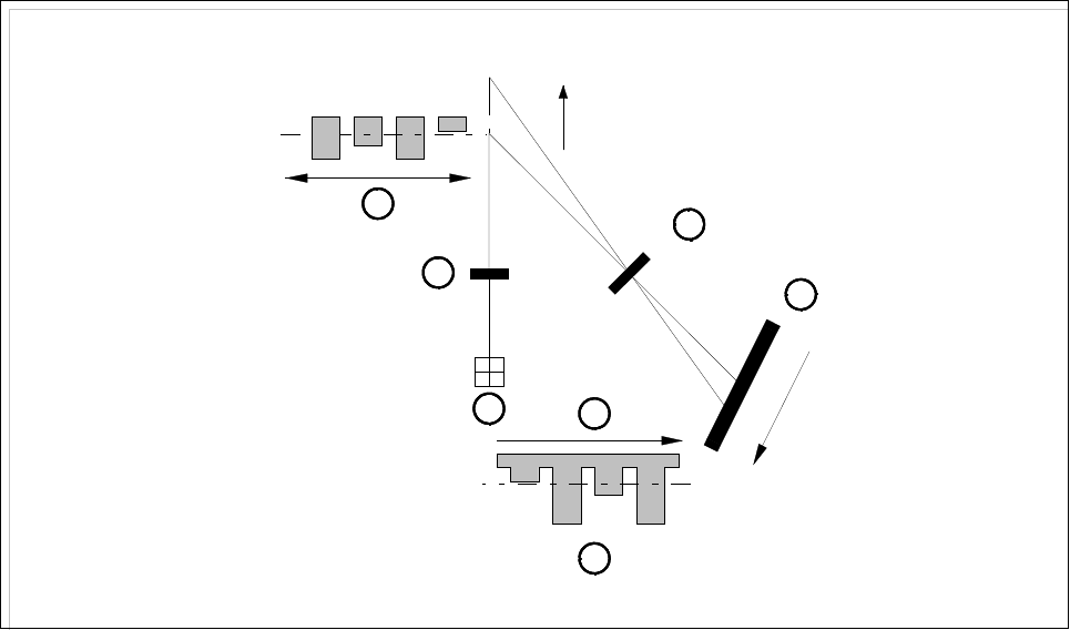
The coplanarity laser module is used for measuring vertical bending in the connection leads of components.
The leads height is measured by a non-contact method working on the principle of laser triangulation.
The placement head picks up the component which is to be checked, centers it optically with the IC camera
and then moves each of its four sides in turn over the stationary laser beam of the coplanarity laser module.
Here each lead is scanned from the bottom up by the laser beam. The laser light scattered by the underside of
the leads is detected by a sensor and serves as a basis for calculating the exact position of the lead with
respect to the board. The positional values thus obtained are then compared with the limit value specified by
the user. If this value is exceeded, the component will be discarded or returned.
Fig. 5.11.1 Laser triangulation principle of measurement
- Key to Fig. 5.11.1
1 Receiver lens 2 Detector
3 Measurement signal 4 Time t
5 Laser 6 Transmitter lens
7 Direction of travel
The coplanarity laser module is used in combination with optical component centering using the vision sys-
tem. Components with bent or missing leads will be detected and discarded as appropriate.
1
2
3
4
5
6
7
z = 0
+Z
+Z’
Z’ = 0

5 Vision Functions SIPLACE 80S-20/F4/F5 User Manual
5.11 Coplanarity Laser Module (SIPLACE 80F4 or 80F5 only) 05/99 Issue from Software Version SR.405.xx
5 - 168 Line engineer
5.11.2 Technical Data
Components: Can be used for gull-wing component shapes
Component size and leads pitch restricted by the
components position recognition system -
in other words, max. size 43.0 mm x 43.0 mm x 11.0mm.
Measurement principle: Non-contact measurement using laser-triangulation
Algorithm functions: JEDEC standard calculation of the placement level; all
deviations will be determined with reference to this level.
If a component is positioned askew in the nozzle, something which
can be caused by an adapter, this will thus have no influence on
the good / bad decision.
Output: < 5 mW
Measuring range: ± 2.5 mm
Laser focus: Elliptical, 50µm x 95µm
Temperature stability: ± 1µm/K
Wavelength: 670 nm
Resolution: 0.25µm
Scanning rate: 10 kHz
Weight: 500 g
Operating temperature: 0°C ... 40
Atmospheric humidity: 5 - 95% non-condensing
Ambient pressure: Atmospheric pressure
Vibration: In accordance with IEC 68-2-6
Mechanical shock: In accordance with IEC 68-2-27
EMC: In accordance with EN 50081-2, emitted interference
(electromagnetic compatibility) In accordance with EN 50082-2, resistance to interference
Degree of protection: IP 64
Dimensions: 118 mm x 30 mm x 125.5 mm
Admissible secondary light: 30.000 lx
Safety: When installed in the machine the coplanarity module corresponds to
Laser class 1
. Outside the machine and without additional
wiring or interference with the safety features the module cannot
function. If the machine’s safety features should be circumvented
it will automatically be deemed to correspond to
Laser class 3B
-
Risk of injury to eyes and skin
and therefore protective measures
as specified in VBG 93 will be required.
SIPLACE 80S-20/F4/F5 User Manual 5 Vision Functions
05/99 Issue from Software Version SR.405.xx 5.11 Coplanarity Laser Module (SIPLACE 80F4 or 80F5 only)
Line engineer 5 - 169
5.11.3 Safety Instructions
DANGER
You must not make any modifications whatsoever to or tamper with the safety features or coplanarity laser
module.
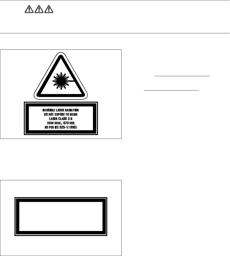
The coplanarity laser module - without safety
features - corresponds to
Laser class 3B
(see
Fig. 5.11.2)
This means
danger to eyes and skin!
For this reason the safety features
should
under no circumstances
be
circumvented.
Fig. 5.11.2 Identification label for
Laser class 3B
To enable the laser module in
Laser class 1
to be operated with no danger to eyes and skin the following
safety features have been installed in the machine:
The interlock line is connected in series with the
switches for the protective cover. Even if the
key-operated switch is used to circumvent the
protective devices this particular protective fea-
ture will not be disabled. This means that the
laser module can be operated
only within the
closed machine.
Fig. 5.11.3 Identification label for
Laser class
1
s