80S-2080F480F5.pdf - 第491页
SIPLACE 80S-20/F4/F5 User M anual 9 Maintenance 05/99 Issue from Software Vers ion SR.405.xx 9.3 Machine B ase 9 - 25 Conn ect the compress ed air s upply ( item 3). Plug i n the cont rol cab le (item 1) . Plug i n the p…
9 Maintenance SIPLACE 80S-20/F4/F5 User Manual
9.3 Machine Base 05/99 Issue from Software Version SR.405.xx
9 - 24
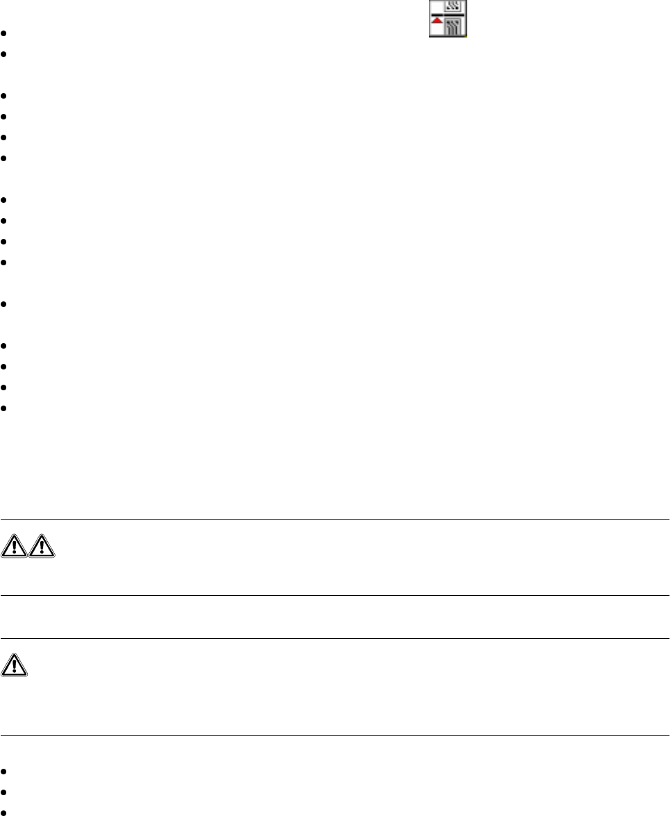
(5) Button for raising and lowering the component table bed
(6) Actuating tube
(7) Fold-down bracket
(8) Holes for the centering pins
(9) Centering pins
(10) Contact surfaces for the slide rails of the component table
(11) Horizontal tensioners
Click on the PAUSE OPERATION icon in the BASIC VIEW menu.
The PCB in progress will be completed. The icons of the SINGLE FUNCTIONS menu will then be acti-
vated.
Click on the desired SINGLE FUNCTIONS GANTRY X icon (gantry 1 or 2).
Click on the GANTRY FUNCTIONS icon.
From this menu, click on the APPROACH SET-UP POSITION button.
The selected placement head will move across the PCB transport to prevent it being damaged when the
component table is changed.
Open protective cover of the selected gantry.
Open the side screens.
Open the horizontal tensioners (item 11)
Pull the two actuating tubes (item 6) towards you at the same time and lift up the bracket (item 7) to lock
the raised component table bed in its top end position.
Hold down the button (item 5) for raising the component table bed (item 4) until the component table bed
reaches its top end position.
Unplug the component table power cable (item 2).
Unplug the component table control cable (item 1).
Disconnect the compressed air supply (item 3).
Remove the component table.
9.3.3.9 Docking the component table
WARNING
Check that the placement head is outside the range of the component table.
CAUTION
When docking the component table, ensure that the table bed is in its top end position and the bracket (item 7)
is folded up.
Cut off the empty tapes for the feeder modules.
Make sure that the contact surface (item 10) for the component table bed is clean.
CAREFULLY push the component table into the placement system.

SIPLACE 80S-20/F4/F5 User Manual 9 Maintenance
05/99 Issue from Software Version SR.405.xx 9.3 Machine Base
9 - 25
Connect the compressed air supply (item 3).
Plug in the control cable (item 1).
Plug in the power cable (item 2) for the component table.
Pull the two actuating tubes (item 6) towards you at the same time and then lower the bracket (item 7) in
order to be able to lower the component table bed.
Check that the centring holes in the component table bed lie precisely over the centering pins of the place-
ment system.
Hold down the button (item 5) until the component table bed reaches its top end position.
Release the button and the component table bed will descend.
Ensure that the centring pins engage in the centring holes in the component table bed and that the compo-
nent table bed is fully lowered.
Fold up the bracket (item 7) of the component table.
Lock the two horizontal tensioners (item 11).
Close the side screens and protective cover.
Press the Start button to start the placement system.
9.3.4 Empty Tape Cutters of the SIPLACE 80S-20/80F
4
NOTE
The empty tape cutters are located on both sides of the PCB transport in the machine base in front of the
changeable components tables (Fig. 9.1.1, page 9 - 3).
9.3.4.1 Emptying the Waste Tape Container
Empty the waste tape container and remove all of the tape pieces in the bottom of the container with the vac-
uum cleaner.
9.3.4.2 Maintenance of the Guide Rail and Rotary Cutter Carriage, Checking the
Cutting Edge
DANGER
Do not carry out any cleaning work with alcohol in the presence of naked lights or fire!
Do not remove the empty tape cutter for this maintenance work as otherwise setting will be necessary when it
is reinstalled. In addition, we recommend you to carry out maintenance of the cutter immediately after mainte-
nance of the components table, since you will not need to remove the feeder modules again from the compo-
nents table.
9 Maintenance SIPLACE 80S-20/F4/F5 User Manual
9.3 Machine Base 05/99 Issue from Software Version SR.405.xx
9 - 26
NOTE
In order to avoid them being damaged, position placement heads 1 and 2 within the PCB transport area. To
do so, slide the corresponding gantry by hand by pressing against a side of the gantry. When carrying out
maintenance work make particularly sure before you switch on the 80S-20 machine that you have the at least
the minimum separation between the gantries. For this reason always position only one gantry by hand over
the board conveyor and then carry out maintenance work on the corresponding empty tape cutter.
Preparatory work
DANGER
• Switch the automatic placement system off at the main switch and disconnect from the power supply.
• Switch off the compressed air supply using the shut-off valve on the compressed air unit.
WARNING
• Wait until the compressed air lines have depressurized. This is indicated when the
cutter bar swings in towards the cutting wheel.
Open the protective covers and the side swivel doors.
Move the corresponding gantry out of the working range.
Remove
– the corresponding component changeover table from the 80 S placement system (see Section
9.3.3.7)
– the corresponding component changeover table from the 80 F placement system (see Section
9.3.3.7) and if a waffle-pack changer is installed, the waffle-pack changer (see Section 9.8).
NOTE
If the wafflepack changer has not yet been run to empty, the assignment of the trays to the track and the
rotational position of the magazines to the trays must not be changed.
Remove the guard plate of the cutter.