80S-2080F480F5.pdf - 第492页
9 Maintenance SIPLACE 80 S-20/F4/F5 User Manual 9.3 Machine Base 05/99 Issue f rom Software Version SR.405.xx 9 - 26 NOTE In order to avoid th em bei ng damaged , positio n placeme nt heads 1 and 2 w ithin the P CB trans…

SIPLACE 80S-20/F4/F5 User Manual 9 Maintenance
05/99 Issue from Software Version SR.405.xx 9.3 Machine Base
9 - 25
Connect the compressed air supply (item 3).
Plug in the control cable (item 1).
Plug in the power cable (item 2) for the component table.
Pull the two actuating tubes (item 6) towards you at the same time and then lower the bracket (item 7) in
order to be able to lower the component table bed.
Check that the centring holes in the component table bed lie precisely over the centering pins of the place-
ment system.
Hold down the button (item 5) until the component table bed reaches its top end position.
Release the button and the component table bed will descend.
Ensure that the centring pins engage in the centring holes in the component table bed and that the compo-
nent table bed is fully lowered.
Fold up the bracket (item 7) of the component table.
Lock the two horizontal tensioners (item 11).
Close the side screens and protective cover.
Press the Start button to start the placement system.
9.3.4 Empty Tape Cutters of the SIPLACE 80S-20/80F
4
NOTE
The empty tape cutters are located on both sides of the PCB transport in the machine base in front of the
changeable components tables (Fig. 9.1.1, page 9 - 3).
9.3.4.1 Emptying the Waste Tape Container
Empty the waste tape container and remove all of the tape pieces in the bottom of the container with the vac-
uum cleaner.
9.3.4.2 Maintenance of the Guide Rail and Rotary Cutter Carriage, Checking the
Cutting Edge
DANGER
Do not carry out any cleaning work with alcohol in the presence of naked lights or fire!
Do not remove the empty tape cutter for this maintenance work as otherwise setting will be necessary when it
is reinstalled. In addition, we recommend you to carry out maintenance of the cutter immediately after mainte-
nance of the components table, since you will not need to remove the feeder modules again from the compo-
nents table.

9 Maintenance SIPLACE 80S-20/F4/F5 User Manual
9.3 Machine Base 05/99 Issue from Software Version SR.405.xx
9 - 26
NOTE
In order to avoid them being damaged, position placement heads 1 and 2 within the PCB transport area. To
do so, slide the corresponding gantry by hand by pressing against a side of the gantry. When carrying out
maintenance work make particularly sure before you switch on the 80S-20 machine that you have the at least
the minimum separation between the gantries. For this reason always position only one gantry by hand over
the board conveyor and then carry out maintenance work on the corresponding empty tape cutter.
Preparatory work
DANGER
• Switch the automatic placement system off at the main switch and disconnect from the power supply.
• Switch off the compressed air supply using the shut-off valve on the compressed air unit.
WARNING
• Wait until the compressed air lines have depressurized. This is indicated when the
cutter bar swings in towards the cutting wheel.
Open the protective covers and the side swivel doors.
Move the corresponding gantry out of the working range.
Remove
– the corresponding component changeover table from the 80 S placement system (see Section
9.3.3.7)
– the corresponding component changeover table from the 80 F placement system (see Section
9.3.3.7) and if a waffle-pack changer is installed, the waffle-pack changer (see Section 9.8).
NOTE
If the wafflepack changer has not yet been run to empty, the assignment of the trays to the track and the
rotational position of the magazines to the trays must not be changed.
Remove the guard plate of the cutter.
SIPLACE 80S-20/F4/F5 User Manual 9 Maintenance
05/99 Issue from Software Version SR.405.xx 9.3 Machine Base
9 - 27
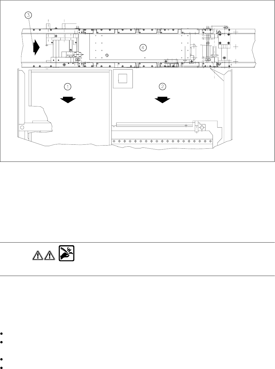
Fig. 9.3.3 Wafflepack changer or component changeover table
- Key to Fig. 9.3.3
1 Wafflepack changer
2 Changeable component table
3 Direction of PCB transport
4 Center conveyor
Checking and replacing the cutter blade and rotary cutter
WARNING
Do not touch the cutting edge of the cutter blade or you risk cutting yourself !
Carry out a visual inspection of the cutter blade and rotary cutter. If the cutting edge is blunt or the cutter blade
in the rotary cutter has worn out, you will need to replace
both
parts each time, as is described in the
Compo-
nents table
section of the service manual. Setting will be required here.
Cleaning and oiling the guide rail, greasing the rotary cutter carriage
There is a risk of cutting yourself on the cutting edge! Wear sturdy work gloves.
Clean the guide rail (see Fig. 9.3.4, page 9 - 28) with alcohol. In particular remove accumulations of grease
and dirt at either end of the carriage path. Apply some WD40 lubricant and corrosion protection agent.
To allow you to reach all points, slide the carriage with the rotary cutter by hand.
Use a brush to apply some WD40 lubricant and corrosion protection agent to the rotary cutter and cutter
blade.