80S-2080F480F5.pdf - 第501页
SIPLACE 80S-20/F4/F5 User M anual 9 Maintenance 05/99 Issue from Software Vers ion SR.405.xx 9.3 Machine B ase 9 - 35 9.3.7 Cleaning the IC Head No zzle Changer (SIPLACE 80F 4 /F 5 ) NOTE Carry ou t maint enance of the n…
9 Maintenance SIPLACE 80S-20/F4/F5 User Manual
9.3 Machine Base 05/99 Issue from Software Version SR.405.xx
9 - 34
9.3.6 Emptying the Rejects Container for the IC Head (SIPLACE 80F
4
/
F
5
)
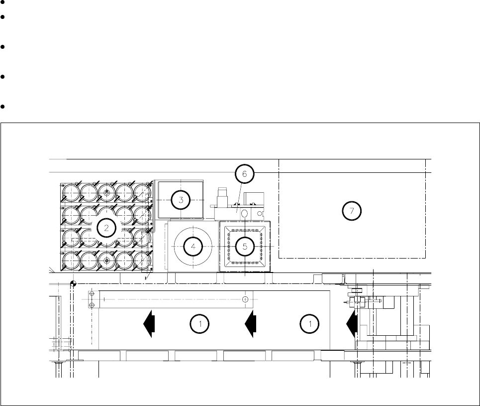
As regards the position of this rejects container at the machine base, please refer to Fig. 9.3.6.
The machine is switched off at the main switch and the sliding safety hoods are open.
Check first whether the z axis (sleeve) is in its top end position. If it is not, this indicates a fault. You should
inform Siemens’ SMD service department.
Move the gantry away from the rejects container by hand. Only hold the gantry and never the placement
head.
Lift the rejects container vertically upwards and off the magnetic disk, making sure that no components
drop into the working area of the machine.
Place the empty container back in the center of the magnetic plate.
Fig. 9.3.6 Emptying the rejects container for the IC head, position at the machine base
- Key to Fig. 9.3.6
1 Direction of PCB transport
2 IC head nozzle changer
3 Rejects container for IC head
4 Flip-chip sensor
5IC sensor
6 Coplanarity module
7 Wafflepack changer
SIPLACE 80S-20/F4/F5 User Manual 9 Maintenance
05/99 Issue from Software Version SR.405.xx 9.3 Machine Base
9 - 35
9.3.7 Cleaning the IC Head Nozzle Changer (SIPLACE 80F
4
/F
5
)
NOTE
Carry out maintenance of the nozzle changer whenever possible in conjunction with maintenance or inspec-
tion of the nozzles since for this work the nozzles have to be removed from the nozzle changer and afterwards
put back in their correct allocations.
The position of the nozzle changer in the machine base is shown in Fig. 9.3.6.
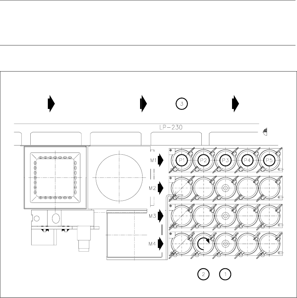
Fig. 9.3.7 Maintenance of the nozzle changer, allocations of nozzle to garage number
- Key to Fig. 9.3.7
1 Cleaning the locating holes
2 Direction of rotation for unlocking the nozzle for removal
3 Direction of PCB transport
M1 - M4 Magazine number
P1 - P5 Nozzle garage number
9 Maintenance SIPLACE 80S-20/F4/F5 User Manual
9.3 Machine Base 05/99 Issue from Software Version SR.405.xx
9 - 36
Starting at the
Gantry 1 functions
menu, select
IC head functions
→
Return
.
In the
Gantry functions
menu, select the
Go to waiting position
option. This moves the IC head to an
area outside of the nozzle changer.
DANGER
Switch off the automatic placement systems at the main switch and disconnect from the power supply.
Open the sliding safety door above the IC head.
Remove the nozzles manually one by one from the nozzle changer.
To do so, place the nozzle removal tool on the nozzle, as shown in Fig. 9.6.8, page 9 - 73. Turn the nozzle
clockwise as far as the stop and until it disengages. Lift away the tool. Now remove the nozzles by hand
from the nozzle changer.
As you remove each nozzle make a note of its garage number and nozzle type, or have them displayed
again following maintenance in the
Nozzle configuration IC-head
menu.
Clean out the locating holes in the nozzle changer with the vacuum cleaner, and clean also in this way the
bearing surface and countersink of each hole, if necessary using a brush and some alcohol. Finally, dry off
the holes.
NOTE:
You have the assignments of the nozzle types to the garage number displayed on the screen in this way:
Gantry 1 functions
menu
→
Nozzle configuration IC head
. The ACTUAL and PROGRAMMED assign-
ments are shown on the screen. Make sure you restore the ACTUAL assignments.
Carry out maintenance on the nozzles whenever possible before replacing the nozzles in the nozzle
changer.
After this, replace the nozzles in the correct allocated positions in the nozzle changer.
When placement is resumed, the actual nozzle will be picked up again automatically. However a precondi-
tion of this is that you have, as described above, returned the nozzle using the
Return nozzle
function.