80S-2080F480F5.pdf - 第529页
SIPLACE 80S-20/F4/F5 User M anual 9 Maintenance 05/99 Issue from Software Version SR.405.xx 9.6 IC Head (SIPLACE 80F4/F5) 9 - 63 9.6 IC Head (SIPLACE 80F 4 /F 5 ) 9.6.1 Prep aratory W ork Select Gantry 1 functions → IC h…

9 Maintenance SIPLACE 80S-20/F4/F5 User Manual
9.5 12x Revolver Head 10000 05/99 Issue from Software Version SR.405.xx
9 - 62
9.5.6.4 Error Messages that Suggest that the Valves are Moving Too Freely
The following error messages can appear during the
reference run
because the valves are moving too freely.
The following error messages can appear during
placement
because the valves are moving too freely.
When rejecting components
During pick-up or placement operation of components:
Depending on the step motor movement you have to differentiate between two cases:
1. Error messages prompted during a step motor movement inbetween 0° and 90°: The valve plunger will be
moved, the vacuum will be switched on or off.
2. Error message prompted during a step motor movement inbetween 90° and 180°:
The valve plunger has been moved, the step motor drive approaches home position.
NOTE
Error message no. 2327 is also prompted if the step motor movement is faulty inbetween 0° and 90°.
9.5.7 12x Revolver Head Nozzle Survey
The nozzles setting instructions for the 12-nozzle revolver head are given in section 17.2.1 of this user man-
ual.
Error number Error message
2311 Valve adjustment drive pickup/placement cannot be initialized
2313 Valve adjustment drive rejection cannot be initialized
Tab. 9.5.1 Error messages prompted during referencing
Error number Error message
2297 SP: Stepping motor for reject defective
Tab. 9.5.2 Error message prompted during placement operation if components are rejected
Error number Error message
2331 SP: Fault in pick-up/place valve actuator during pick-up
2334 SP: Fault in pick-up/place valve actuator during placement
Tab. 9.5.3 Error messages prompted during pick-up/placement operation with the step motor moving inbetween 0° and 90°
Error number Error message
2327 Star can’t be turned due to pick-up/place valve actuator
Tab. 9.5.4 Error message prompted during pick-up/placement operation with the step motor moving inbetween 90° and 180°
SIPLACE 80S-20/F4/F5 User Manual 9 Maintenance
05/99 Issue from Software Version SR.405.xx 9.6 IC Head (SIPLACE 80F4/F5)
9 - 63
9.6 IC Head (SIPLACE 80F
4
/F
5
)
9.6.1 Preparatory Work
Select
Gantry 1 functions
→
IC head functions
→
Return
.
Switch the machine off at the main switch. Open the safety hoods / swivel door.
Observe the safety instructions for the coplanarity laser module in Section 9.1
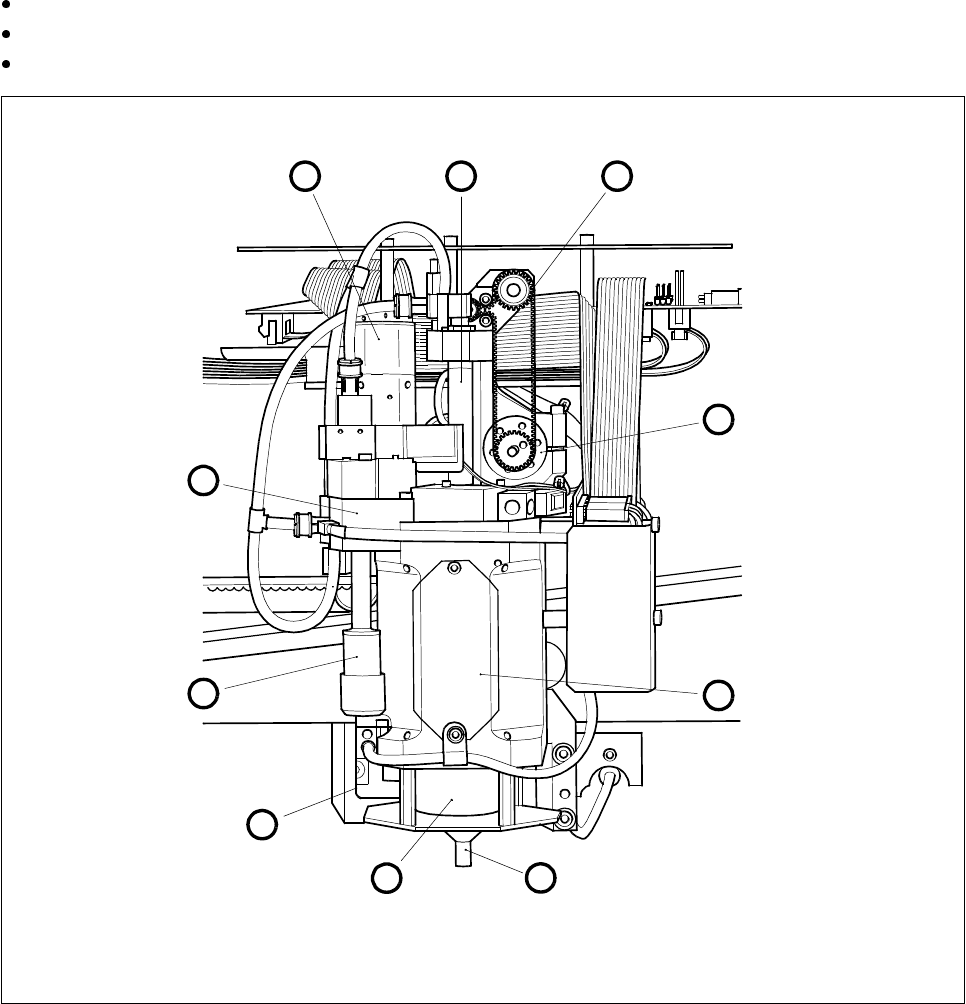
Fig. 9.6.1 Location of the modules requiring maintenance in the IC head
- Key to Fig. 9.6.1
1 Motor/tacho, dr axis 6 Nozzle
2 Venturi nozzle, installed 7 Cover
3 Silencer 8 Motor/tacho, z axis
4 Cover 9 Toothed belt, z axis
5 Encoder flange 10 IC-head sleeve, complete
1 10 9
8
7
6
5
4
3
2
9 Maintenance SIPLACE 80S-20/F4/F5 User Manual
9.6 IC Head (SIPLACE 80F4/F5) 05/99 Issue from Software Version SR.405.xx
9 - 64
Check to see whether the z axis is in its top end position and move the IC head by hand to a favorable
working position by pressing on a suitable side of the gantry carriage, thus ensuring that the head does not
get damaged.
Currently when the
Go to service position
option in the
Gantry functions
menu is selected the service posi-
tion of the star head will be approached. The
IC head service position
button will be available at a later date.
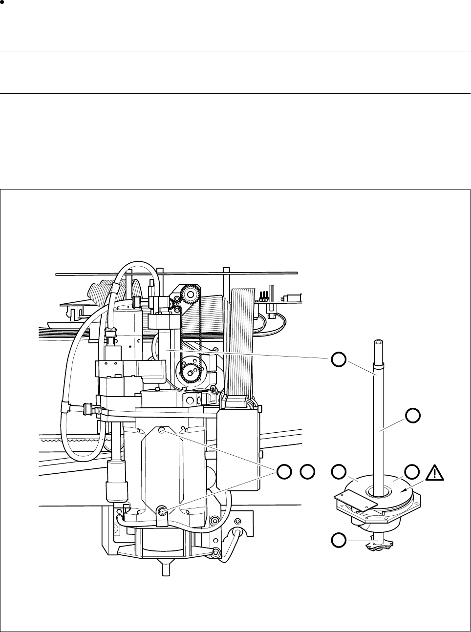
9.6.2 Oiling the Sleeve and Cleaning the Encoder Disk
Carry out maintenance, as shown in Fig. 9.6.2.
Fig. 9.6.2 Oiling the sleeve and cleaning the encoder disk
A D
,
C
2
1
B
B