80S-2080F480F5.pdf - 第538页
9 Maintenance SIPLACE 80 S-20/F4/F5 User Manual 9.6 IC Head (SIPLACE 80F4/F5) 05/99 Issue from Software Version SR.405.xx 9 - 72 - Sequence of work in Fig. 9.6.7 A Clean the o-ring with alco hol and gr ease spari ngly wi…
SIPLACE 80S-20/F4/F5 User Manual 9 Maintenance
05/99 Issue from Software Version SR.405.xx 9.6 IC Head (SIPLACE 80F4/F5)
9 - 71
- Key to Fig. 9.6.6
1 View in the direction of fitting of the placement head
2 Vacuum nozzle
3 IC head
4 Valve (vacuum)
5Block
6 Compressed air supply line
- Sequence of work in Fig. 9.6.6
A Push the red locking ring down onto the collet bush and pull out the compressed air hose.
B Disconnect the plug connection at the solenoid valve.
C Unscrew and remove the two M3 hexagon socket screws which fasten the valve with block to the vacuum
generator.
D Lift the solenoid valve together with the block upwards and off.
E Pull the vacuum nozzle vertically upwards and out and carry out maintenance on it (see Section 9.6.5.2).
F Fit the vacuum nozzle back in the reverse sequence.
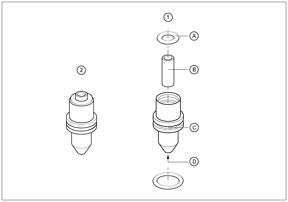
Fig. 9.6.7 Cleaning the vacuum nozzle and o-rings
- Key to Fig. 9.6.7
1 Maintenance of the vacuum nozzle assembly
2The vacuum nozzle assembly removed

9 Maintenance SIPLACE 80S-20/F4/F5 User Manual
9.6 IC Head (SIPLACE 80F4/F5) 05/99 Issue from Software Version SR.405.xx
9 - 72
- Sequence of work in Fig. 9.6.7
A Clean the o-ring with alcohol and grease sparingly with Unisilkon L250L.
B Clean outside and inside diameter.
C Clean the annular groove.
D Clean the venturi nozzle.
Fit the vacuum generator back in the reverse sequence.
Turn on the compressed air at the stop valve of the compressed air unit and switch the machine on.
Check the operating pressure (see Fig. 9.3.5 and Fig. 9.3.6) and fit the cover back on the machine base.
9.6.6 Maintenance of the Nozzles
Carry out maintenance of the nozzles following maintenance of the pick-up star.
9.6.6.1 Preparatory Work
NOTE
The item numbers of the nozzles and diaphragms will be found in Section 9.6.7, Page 77.
Material and equipment: Nozzle removal tool, from item no. 00311448-01
You will already have returned the current nozzle to the nozzle changer by selecting
Gantry 1 functions
→
IC head functions
→
Return (nozzle)
.
Make a note of the nozzle types and corresponding garage numbers. You will need these allocations later
for refitting the nozzles. Specification of the garage numbers is shown in Fig. 9.6.11.
Remove all nozzles from the nozzle changer with the aid of the nozzle removal tool. Proceed as shown in
Fig. 9.6.8.
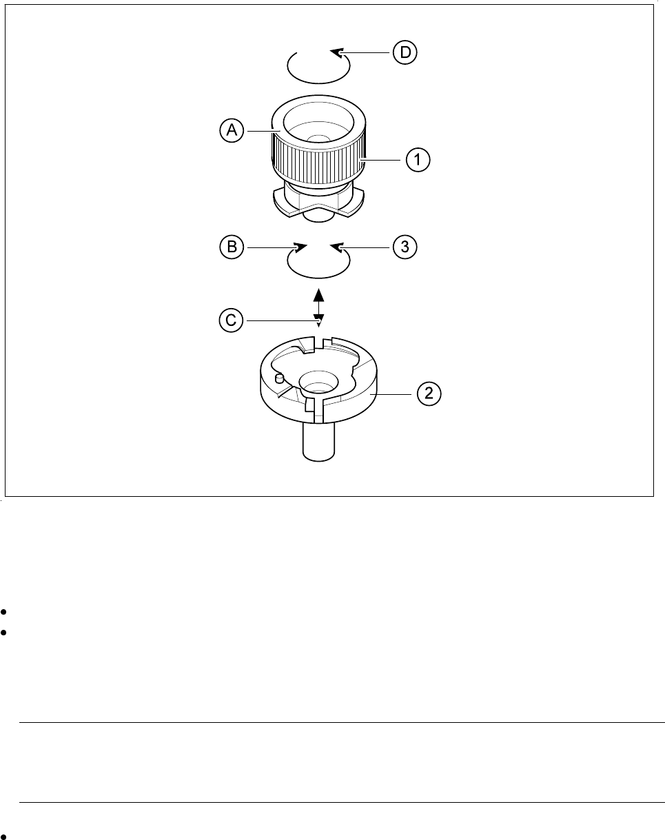
- Key to Fig. 9.6.8
1 Nozzle removal tool
2 Nozzle in the nozzle changer
3 Direction of rotation: lock the nozzle after inserting it in the nozzle changer
- Sequence of work in Fig. 9.6.8 - nozzle removal
A Insert the tool into the nozzle.
B Turn the tool clockwise to release the nozzle in the nozzle changer.
C Lift the released nozzle out using the tool.
D Hold the nozzle firmly and turn the tool counter-clockwise to remove.
SIPLACE 80S-20/F4/F5 User Manual 9 Maintenance
05/99 Issue from Software Version SR.405.xx 9.6 IC Head (SIPLACE 80F4/F5)
9 - 73
Fig. 9.6.8 Removing the nozzle from the nozzle changer
9.6.6.2 Checking and Maintaining the Nozzles
Carry out maintenance of the nozzles as shown in Fig. 9.6.9.
Check the nozzles and the diaphragms and replace any damaged diaphragm.
Please refer to Fig. 9.6.10 for the procedure for replacing diaphragms. The item numbers for the dia-
phragms are given in section 17.2.2. For maintenance of the diaphragms you will require talcum powder
(see Table 9 - 14).
NOTE
Rubbing over with talcum prevents components sticking to the diaphragm after being set down on the
board. The diaphragm must not come into contact with spirit or alcohol.
Check the suction faces of the nozzles without diaphragm: if you detect damage use the corresponding
new nozzles. For the item numbers, see section 17.2.2.