80S-2080F480F5.pdf - 第589页
SIPLACE 80 S20/F4/F5 User Manual 10 Component Handling 05/99 Issue from Software Version SR.405.xx 10.5 Reel Container (New Group) 10 - 17 10.5 Reel Co nt ainer (New Group) 10.5.1 G eneral Information T ap es with a ree …
10 Component Handling SIPLACE 80 S20/F4/F5 User Manual
10.4 Empty Tape Cutter on SIPLACE 80S-20/F4 Automatic Placement Machines 05/99 Issue from Software Version SR.405.xx
10 - 16
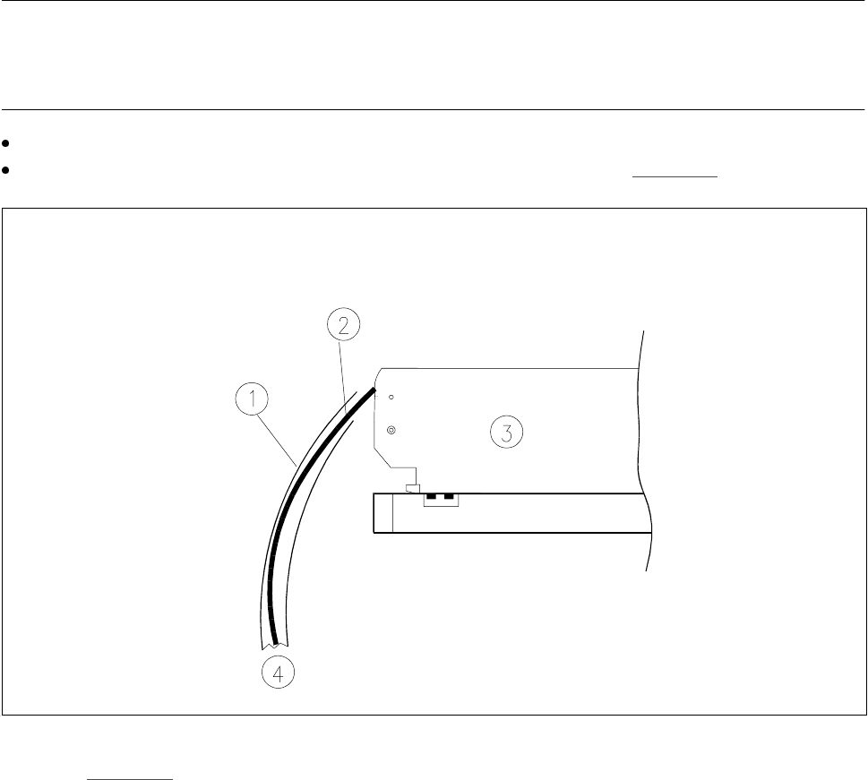
10.4.2 Inserting the Tape into the Tape Cutter
PLEASE NOTE
On SIPLACE 80S-20/F
4
automatic placement systems, only use the tape feeder modules specified for these
machines. The used tape channel which removes the used tape is located upstream of the feeder modules.
Insert the tape into the feeder as described in the corresponding section.
Guide the used tape into the used tape channel of the cutter as described in Fig. 10.4.2
Fig. 10.4.2 Inserting the tape into the tape cutter
-Key to Fig. 10.4.2
1 Used tape channel 2 Used tape
3 Tape feeder module 4 To tape cutter
SIPLACE 80 S20/F4/F5 User Manual 10 Component Handling
05/99 Issue from Software Version SR.405.xx 10.5 Reel Container (New Group)
10 - 17
10.5 Reel Container (New Group)
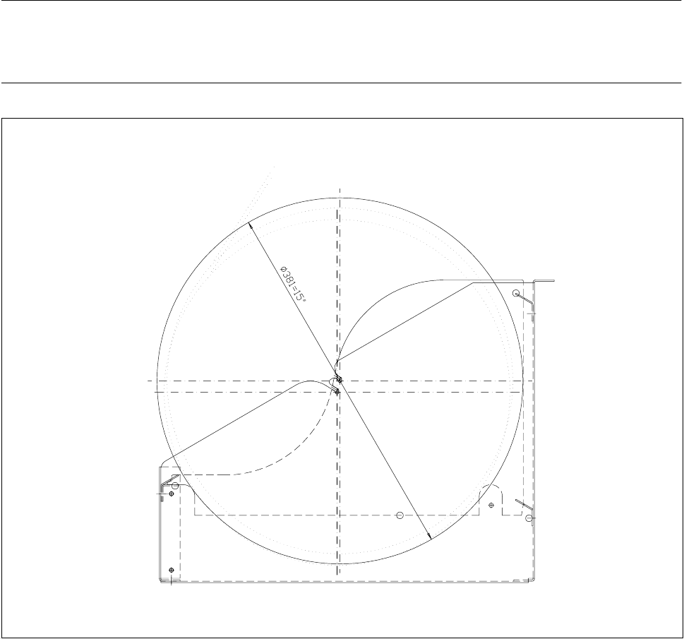
10.5.1 General Information
Tapes with a reel diameter of up to 15" can be used.
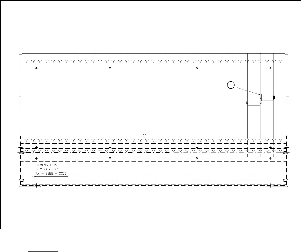
10.5.2 Overview
Fig. 10.5.1 Reel container - viewed from the top
-Key to Fig. 10.5.1
1 Insertion spindles are allocated to the tape modules
– The distance between spacers is halved (15.8 mm)
– Reel diameters of up to 15" can be used
– Use only 15" reels in the upper slot or seating on the rods
– Dividing walls are backward-compatible
10 Component Handling SIPLACE 80 S20/F4/F5 User Manual
10.5 Reel Container (New Group) 05/99 Issue from Software Version SR.405.xx
10 - 18
NOTE
PLEASE NOTE
With large tape reels (> 5"), use insertion spindles to ensure that the conveyors operate reliably.
Fig. 10.5.2 Reel container - side view (reel inserted)