80S-2080F480F5.pdf - 第62页
1 Operational Safety SIPLACE 80S-20/F4/F5 User Manual 1.2 Safety equipment 05/99 Issue from Software Version SR.405.xx 1 - 24 1.2.1. 1 General The gantr y positi oning range is cov ered by two protec tive co vers. If yo …
SIPLACE 80S-20/F4/F5 User Manual 1 Operational Safety
05/99 Issue from Software Version SR.405.xx 1.2 Safety equipment
1 - 23
1.2 Safety equipment
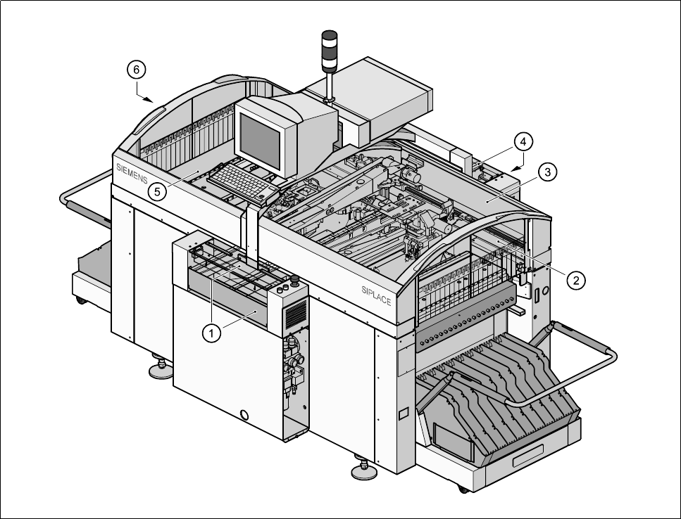
1.2.1 Protective covers
Fig. 1.2.1 SIPLACE 80S20/F
4
/F
5
safety equipment
- Key to Fig. 1.2.1
1 Cover and guard on the input belt 2 Safety discs, righthand side
3 Protective cover 4 Cover and guard on the output belt
5 Protective cover 6 Safety discs, lefthand side
1 Operational Safety SIPLACE 80S-20/F4/F5 User Manual
1.2 Safety equipment 05/99 Issue from Software Version SR.405.xx
1 - 24
1.2.1.1 General
The gantry positioning range is covered by two protective covers. If you want to open the protective covers,
first press the Stop button (item 1 in Fig. 1.2.2) or the emergency stop mushroom-head push-button (item 2 in
Fig. 1.2.2). The power to the gantry axes will be switched off and the gantries will stop immediately.
If you open one of the protective covers or a guard on the incoming or outgoing conveyor, the power to the
gantry axes will be switched off and they will stop immediately.
If the key switch is closed (position
I
), you can continue to pace the star at reduced speed while the protective
covers are open.
Placement will stop if you press the emergency stop mushroom-head push-button. You can then either cancel
or continue placement of the PCB. The protective covers at the sides can be opened in order to refill with
components when the machine has stopped.
WARNING
The protective covers must only be opened, with the key switch closed (position
I
), by appropriately qualified
and trained personnel.
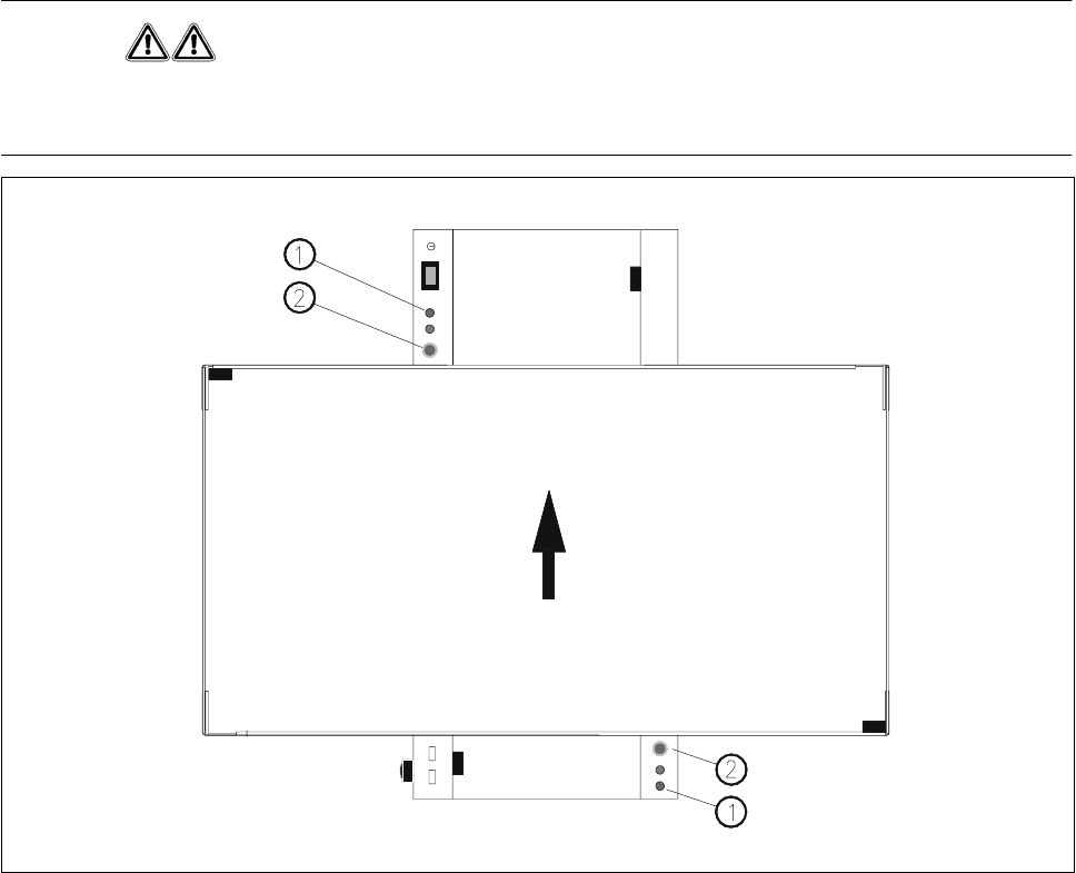
Fig. 1.2.2 Stop and emergency stop mushroom-head push-button
- Key to Fig. 1.2.2
1 Stop button 2 Emergency stop mushroom-head push-button
SIPLACE 80S-20/F4/F5 User Manual 1 Operational Safety
05/99 Issue from Software Version SR.405.xx 1.2 Safety equipment
1 - 25
1.2.2 Guard on the input / output conveyor
DANGER
The guard must always be set to the height of the PCB to be processed. Ensure that the gap between the guard
and the safety bar is as small as possible.
Guards are fitted on the input and output belts of the PCB conveyor.
The height of the guard must be set using the slots so that the processed PCB can travel through.
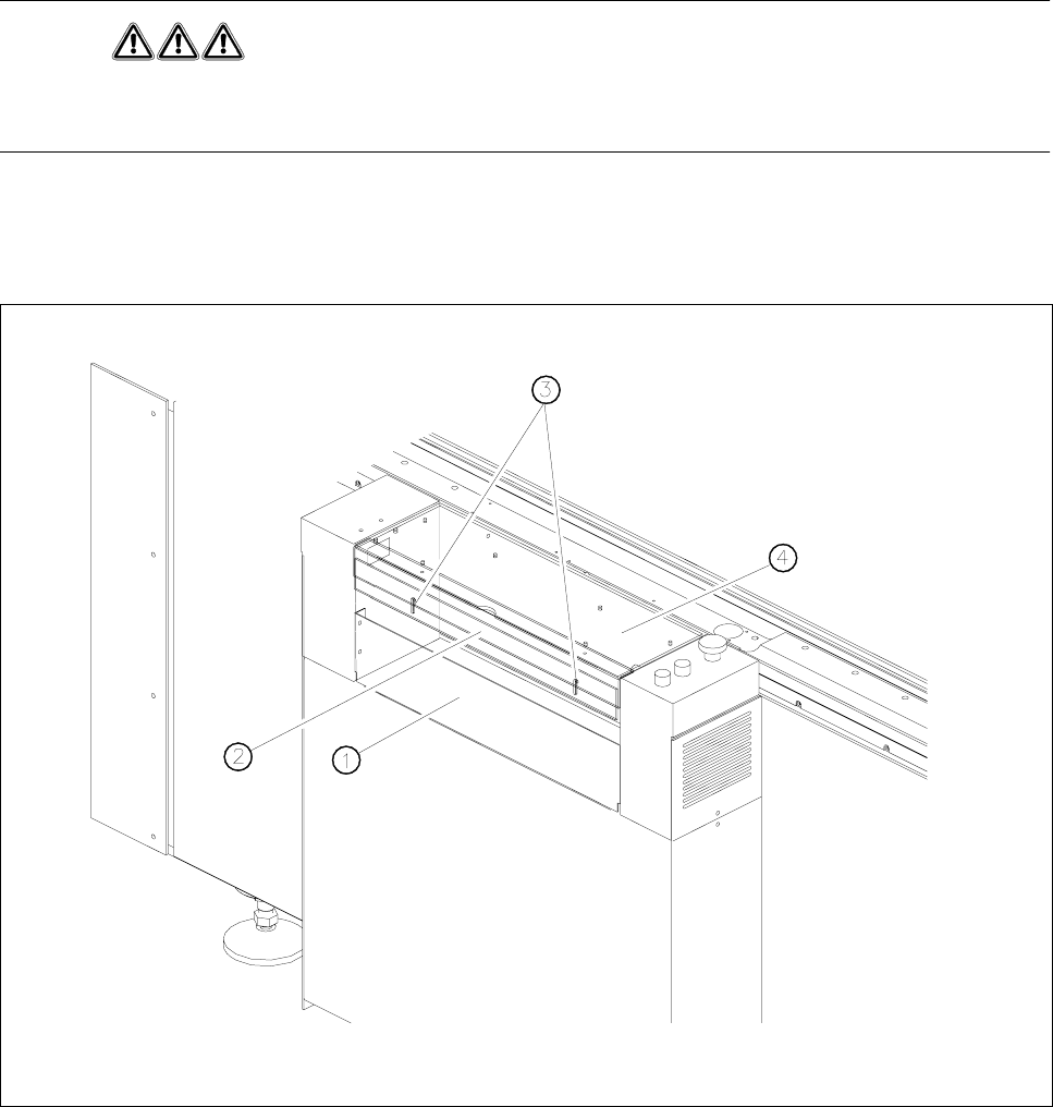
Fig. 1.2.3 Guard on SIPLACE 80S20/F
4
F
5
- Key to Fig. 1.2.3
1 Safety bar (fixed) 2 Guard (adjustable)
3 Slots for adjusting the height 4 Cover