80S-2080F480F5.pdf - 第649页
SIPLACE 80S-20/F4/F5 User M anual 11 Station Extensions/Options 05/99 Issue from Software Version SR.405.xx 11.6 Ceramic Substrate Centering 11 - 33 This obli que lighti ng unit can be s witched on as an alternati ve to …
11 Station Extensions/Options SIPLACE 80S-20/F4/F5 User Manual
11.6 Ceramic Substrate Centering 05/99 Issue from Software Version SR.405.xx
11 - 32
11.6.4 Technical Data
11.6.5 Optical Centering with Oblique Lighting
11.6.5.1 General Comments
With optical ceramic substrate centering the special conditions of the ceramic substrate must be taken into
consideration. Contrast will be heavily dependent on the paste which is used for the alignment structure, on
the clear surroundings of the alignment structure, and on the type of illumination.
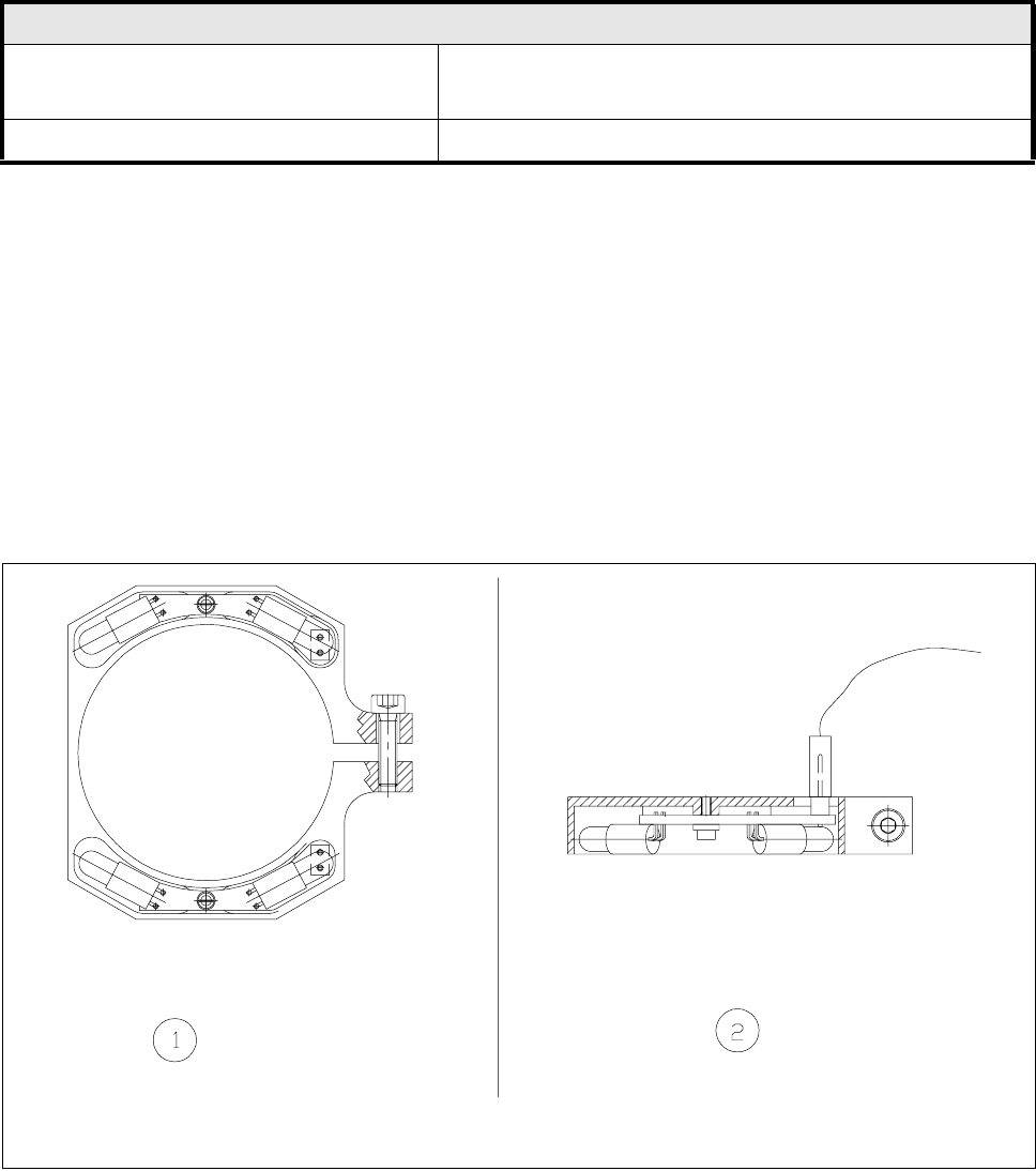
The oblique lighting facility is located on the front part of the UP camera (undergantry camera).
Fig. 11.6.3 Oblique light lighting unit for the UP camera
- Key to Fig. 11.6.3
1 Top view of the oblique lighting unit 2 Side view of the oblique lighting unit
Ceramic substrate centering
Usable substrate sizes 50 mm x 50 mm (2" x 2") up to a max. of 4" x 7"
(Further sizes on request)
Compressed air supply 5 bar
SIPLACE 80S-20/F4/F5 User Manual 11 Station Extensions/Options
05/99 Issue from Software Version SR.405.xx 11.6 Ceramic Substrate Centering
11 - 33
This oblique lighting unit can be switched on as an alternative to the existing lighting (see the table in Section
11.6.2).
NOTE
The oblique lighting unit can only be used with the undergantry camera.
11.6.5.2 Fiducial Recommendations for Ceramic Substrates
With ceramic substrates the contrast between the carrier material and the conductor layer is generally very
low. For this reason when fiducials are selected, certain criteria must be observed regarding the shape and
structure of the fiducials. Our recommendations regarding the shape and structure of the fiducials are given
below.
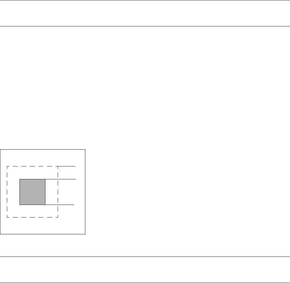
l Shape of the fiducial
We suggest a rectangle or square with a side length of >
1 mm and a free space around it of not less than
0.5 mm.
Fig. 11.6.4 Recommended shape for a fiducial
NOTE
Simple crosses are also suitable, but do require more space.
0.5 mm
1.0 mm
11 Station Extensions/Options SIPLACE 80S-20/F4/F5 User Manual
11.6 Ceramic Substrate Centering 05/99 Issue from Software Version SR.405.xx
11 - 34
l Structure of the fiducial
Proposal 1
Structure of the
fiducial
Black resistor paste as background. Conductor paste printed onto this as fiducial.
Recommendation Background 0.75 mm larger than the fiducial on all sides.
Type of lighting Normal light
Advantage Good contrast; good definition
Reference Conductor layer
Assessment This combination gives the best results. Highly recommended.
Proposal 2
Structure of the
fiducial
Fiducial made of conductor track material; for example, 6119 and with passivation
glass 4330 overprinted.
Type of lighting Oblique light
Advantage No additional operational step necessary
Reference Conductor layer
Assessment Fiducials are not so well defined as with Proposal 1. Recommended.
Proposal 3
Structure of the
fiducial
Fiducials made of the conductor track layer against a background of exposed ceramic
Type of lighting Oblique light or normal light (depending on the paste)
Advantage No additional operational step necessary
Reference Conductor layer
Comment Fiducials are not so well defined as with Proposal 2.
Fiducial imaging depends on the surrounding free area. Each circuit may need to be
taught separately.
Assessment Recommended with qualifications.