80S-2080F480F5.pdf - 第653页
SIPLACE 80S-20/F4/F5 User M anual 11 Station Extensions/Options 05/99 Issue from Software Version SR.405.xx 11.7 Dispenser Flux Application Unit for SIPLACE 80F4/F5 11 - 37 The flip- chip comp onent is placed i nto the p…
11 Station Extensions/Options SIPLACE 80S-20/F4/F5 User Manual
11.7 Dispenser Flux Application Unit for SIPLACE 80F4/F5 05/99 Issue from Software Version SR.405.xx
11 - 36
11.7.2 Function
The centrifuge tube is filled with flux and functions as a reservoir. The flux is sucked into the syringe via the
valve by means of a pump. The syringe now dispenses the preset amount of flux onto the placement position
via the valve and the tip of the dispensing needle.
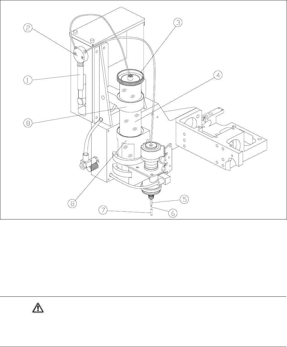
Fig. 11.7.1 Flux application - overview
- Key to Fig. 11.7.1
1Syringe 2Valve
3 Reservoir lid 4 Reservoir (centrifuge tube)
5 Centering nozzle 6 Tip of the dispensing needle
7 Cover cap 8 Holder
CAUTION
If you expect the flux application unit to remain out of use for some time (more than approximately 1 hour), the
cover cap must be pulled over the centering nozzle. This prevents the flux crystallizing and clogging the cen-
tering nozzle.

SIPLACE 80S-20/F4/F5 User Manual 11 Station Extensions/Options
05/99 Issue from Software Version SR.405.xx 11.7 Dispenser Flux Application Unit for SIPLACE 80F4/F5
11 - 37
The flip-chip component is placed into the placement position and held there for a specified period of time so
that the flux can dry to touch-dry.
Fig. 11.7.2 Sketch diagram of a component with flux
- Key to Fig. 11.7.2
1 Flux flows towards the leads
The PCB then remains in the machine for a variable period in order to ensure that the flux has dried fully.
Input of the requisite parameters is described in Section 11.7.6.1, ’Package Form List and Parameters’.
11.7.3 Refilling with Flux
When the quantity of flux in the reservoir is getting low a warning is issued at the station computer. Even after
this warning it is possible to continue placement for a while. You should not allow placement to continue until
the reservoir is empty otherwise unwanted downtimes may be the result.
NOTE
The reservoir must be filled outside the machine to prevent any flux getting spilt in the machine.
Move the fluxer head into the
Refill position
. See Section 11.7.6.4 "Single Functions"
Pull the reservoir upwards and out of the holder. Twist off the reservoir lid. See Fig. 11.7.1 "Flux application
- overview"
Top up the reservoir with flux, replace the lid and put the reservoir back in its holder. See Fig. 11.7.1 "Flux
application - overview". Make sure that the reservoir is seated firmly in the holder.
Using the Single functions, rinse the flux applicator head until the hose and the syringe contain no more air
and the flux emerges in a continuous stream. See Section 11.7.6.4 "Single Functions".
PLEASE NOTE
In all your work, make sure that there are no bubbles of air anywhere in the dispensing needle.
1
11 Station Extensions/Options SIPLACE 80S-20/F4/F5 User Manual
11.7 Dispenser Flux Application Unit for SIPLACE 80F4/F5 05/99 Issue from Software Version SR.405.xx
11 - 38
11.7.4 Changing the Syringe
During normal operation it will not be necessary to change the syringe. You may however need to remove or
replace the syringe during servicing work.
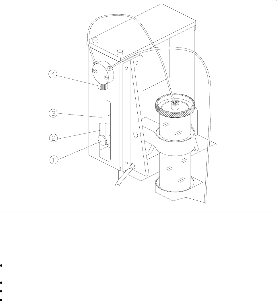
Fig. 11.7.3 Changing the syringe
- Key to Fig. 11.7.3
1 Knurled screw 2 Dosing plunger
3 Syringe 4 Unscrew retaining nut
Under
Single functions
bring the flux into the
Refill position
. See Section 11.7.6.4 "Single Functions".
The dosing plunger of the syringe now moves downwards.
Undo the knurled screw on the dosing plunger.
Slide the dosing plunger upwards. This empties the syringe and the flux is forced back into the reservoir.
Unscrew and remove the retaining nut together with the syringe.