80S-2080F480F5.pdf - 第657页
SIPLACE 80S-20/F4/F5 User M anual 11 Station Extensions/Options 05/99 Issue from Software Version SR.405.xx 11.7 Dispenser Flux Application Unit for SIPLACE 80F4/F5 11 - 41 Loosen the 4 fixi ng scr ews for the r ear cov …
11 Station Extensions/Options SIPLACE 80S-20/F4/F5 User Manual
11.7 Dispenser Flux Application Unit for SIPLACE 80F4/F5 05/99 Issue from Software Version SR.405.xx
11 - 40
Loosen the centering nozzle.
Pull the cylinder cover and the dispensing needle away from the cylinder and pull out the entire dispensing
needle from the cylinder.
Disconnect the end of the hose of the dispensing needle from the valve of the metering pump.
Thread the new dispensing needle through the cylinder cover and through the cylinder and into the center-
ing nozzle. The tip of the dispensing needle must protrude approximately 3 mm from the centering nozzle.
Tighten the centering nozzle once more.
Push the cylinder cover onto the cylinder.
Check the distance between the dispensing needle and the PCB. Push the piston down as you do so. The
distance must be approximately 1 mm.
If this distance is not correct, it must be reset.
11.7.5.1 Setting the Distance Between the Dispensing Needle and the PCB
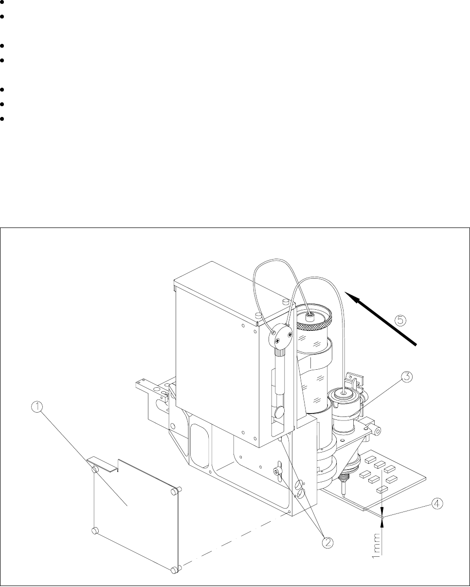
Fig. 11.7.5 11.7.5 Setting the distance between the dispensing needle and the PCB
- Key to Fig. 11.7.5
1 Rear cover with 4 fixing screws 2 2 fixing screws for the flux application unit
3 Lifting piston 4 Set the distance to 1 mm from the PCB
5 Push the flux application unit against the stop

SIPLACE 80S-20/F4/F5 User Manual 11 Station Extensions/Options
05/99 Issue from Software Version SR.405.xx 11.7 Dispenser Flux Application Unit for SIPLACE 80F4/F5
11 - 41
Loosen the 4 fixing screws for the rear cover of the flux application unit and then remove the cover.
Loosen the two fixing screw in the slots.
Push the piston down and adjust the flux application unit so that the distance between the tip of the dis-
pensing needle and the PCB is 1 mm.
Push the flux application unit against the lateral stop and tighten the fixing screws.
Fit the rear cover.
11 Station Extensions/Options SIPLACE 80S-20/F4/F5 User Manual
11.7 Dispenser Flux Application Unit for SIPLACE 80F4/F5 05/99 Issue from Software Version SR.405.xx
11 - 42
11.7.6 User Interface
NOTE
For the flip-chip component to be assembled and provided with flux, a placement program with flip-chip com-
ponents must be written in the line computer and sent to the station computer. See the UNIX user‘s manual.
The
Fluxing
option must be activated under
Machine options
in the station computer. See Section 2.4.4,
’The Options Menu’ of the SIPLACE 80S-20/F
4
/F
5
user‘s manual.
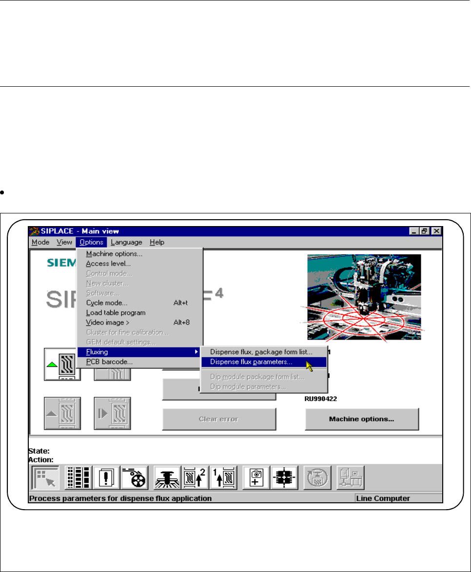
11.7.6.1 Package Form List and Parameters
In order to apply flux to a board for the purpose of placing flip chips, at the station computer you must add the
process data to a list and also enter general parameters regarding fluxing.
Select the submenu
Fluxing
in the
Options
menu.
Fig. 11.7.6 Fluxing option
F