80S-2080F480F5.pdf - 第67页
SIPLACE 80S-20/F4/F5 User M anual 1 Operational Safety 05/99 Issue from Software Version SR.405.xx 1.2 Safety equipment 1 - 29 Fig. 1.2.5 SIPLACE 80S-20/F 4 /F 5 safety circ uits S t art button p ressed Emergenc y stop b…
1 Operational Safety SIPLACE 80S-20/F4/F5 User Manual
1.2 Safety equipment 05/99 Issue from Software Version SR.405.xx
1 - 28
1.2.4 Safety circuits
SIPLACE 80S-20/F
4
/F
5
automatic placement systems have two separate safety circuits which are monitored
by protective contactor combinations K1 and K2. Both protective contactor combinations are incorporated into
the power supply (see item 14 and 15 in Fig. 1.2.4).
DANGER
Automatic placement systems from the SIPLACE family are powered with 3x400VAC ± 10%, 50/60Hz mains
voltage.
This means that parts of the system carry potentially fatal voltages - even when switched off at the main switch.
Death, serious injury or considerable damage may result if these automatic placement systems are handled
incorrectly.
Always follow the applicable accident prevention and DIN regulations (particularly DIN EN 60204, part 1) and
the applicable regulations in your own country.
The guard over the power supply must ONLY be opened by appropriately qualified and trained personnel.
Protective contactor combinations K1 and K2 monitor the following circuits:
K1: Emergency stop circuit, safety circuits for the component tables or wafflepack changer,
protective cover switch and the enable software signal
K2: Emergency stop circuit, K1 protective contactor combination, software enable signal and key switch
K1 or K2 is triggered if any of these functions fail. The mains voltage to the heavy current transformer that
supplies the gantry axis motors will be interrupted. The voltage to the star-type motor for the revolver head is
reduced from 70V to 10V. The dp and dR axes of the placement heads continue to be supplied with 30V. The
next diagram illustrates the various statuses of K1 and K2 and their effects on the axes and the PCB conveyor
components.
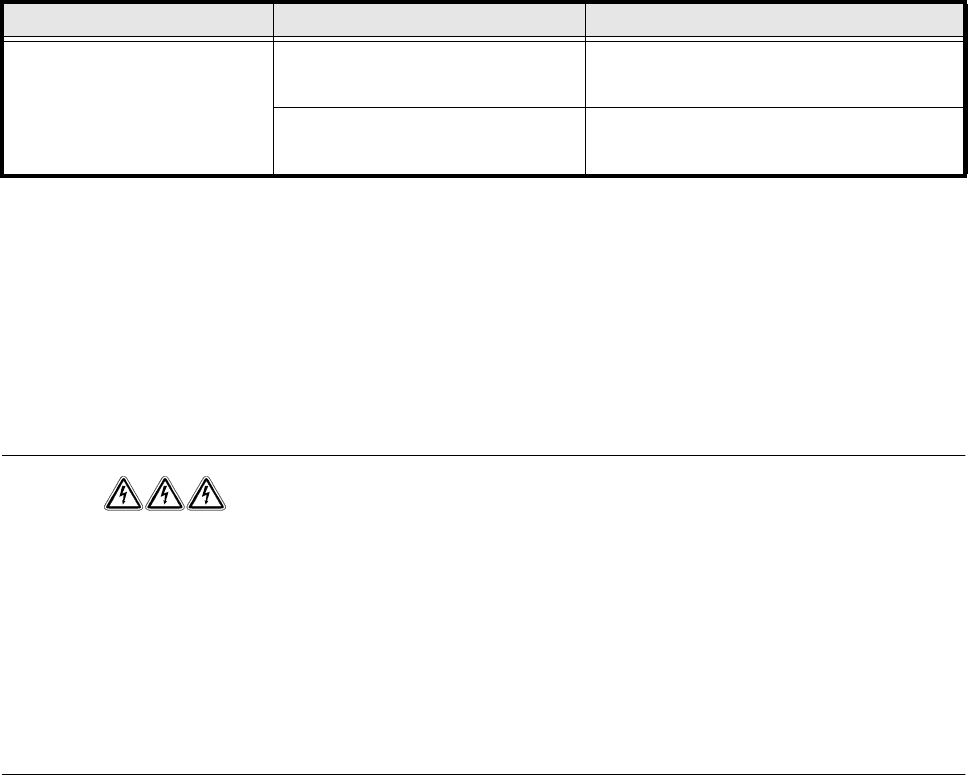
Protective cover open Close the cover Close the protective cover (item 9, 10, 11 or
12 in
Fig. 1.2.4)
Press the Start button Press the green Start button (item 2 or 5 in
Fig. 1.2.4)
Status Display on screen Action required
Tab. 1.2 - 1 Screen displays when the emergency stop mushroom-head push-button is pressed or protective cover is opened
SIPLACE 80S-20/F4/F5 User Manual 1 Operational Safety
05/99 Issue from Software Version SR.405.xx 1.2 Safety equipment
1 - 29
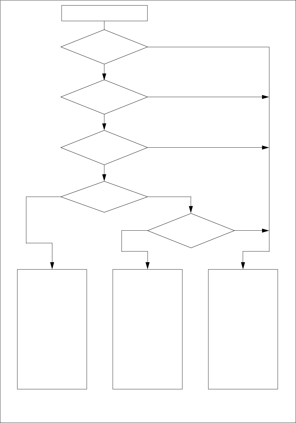
Fig. 1.2.5 SIPLACE 80S-20/F
4
/F
5
safety circuits
Start button pressed
Emergency stop button
pressed?
Protective cover open ?
Key switch
closed (positionI)?
No
Component table safety
circuit interrupted?
Yes
No
No
Yes
Yes
No
Active
K1 *) Yes
K2 *) Yes
Voltage
y axis 100 V
x axis 100 V
Star axis 100 V
dp axis 30 V
z axis 30 V
Active
PCB conveyor Yes
PCB clamping deviceYes
Width adjustment Yes
PCB stopper Yes
Tape cutter Yes
Yes
Active
K1 *) No
K2 *) Yes
Voltage
y axis 0 V
x axis 0 V
Star axis **) 10 V
dp axis 30 V
z axis 30 V
Active
PCB conveyor Yes
PCB clamping device No
Width adjustment Yes
PCB stopper No
Tape cutter No
Active
K1 *) No
K2 *) No
Voltage
y axis 0 V
x axis 0 V
Star axis **) 10 V
dp axis 30 V
z axis 30 V
Active
PCB conveyor No
PCB clamping device No
Width adjustment No
PCB stopper No
Tape cutter No
*) K1, K2 protective contactor combination
**) The maximum current is limited by a 4.7 Ohm resistor.
Compressed air
min. 5.1 bar?
Yes
No
1 Operational Safety SIPLACE 80S-20/F4/F5 User Manual
1.2 Safety equipment 05/99 Issue from Software Version SR.405.xx
1 - 30
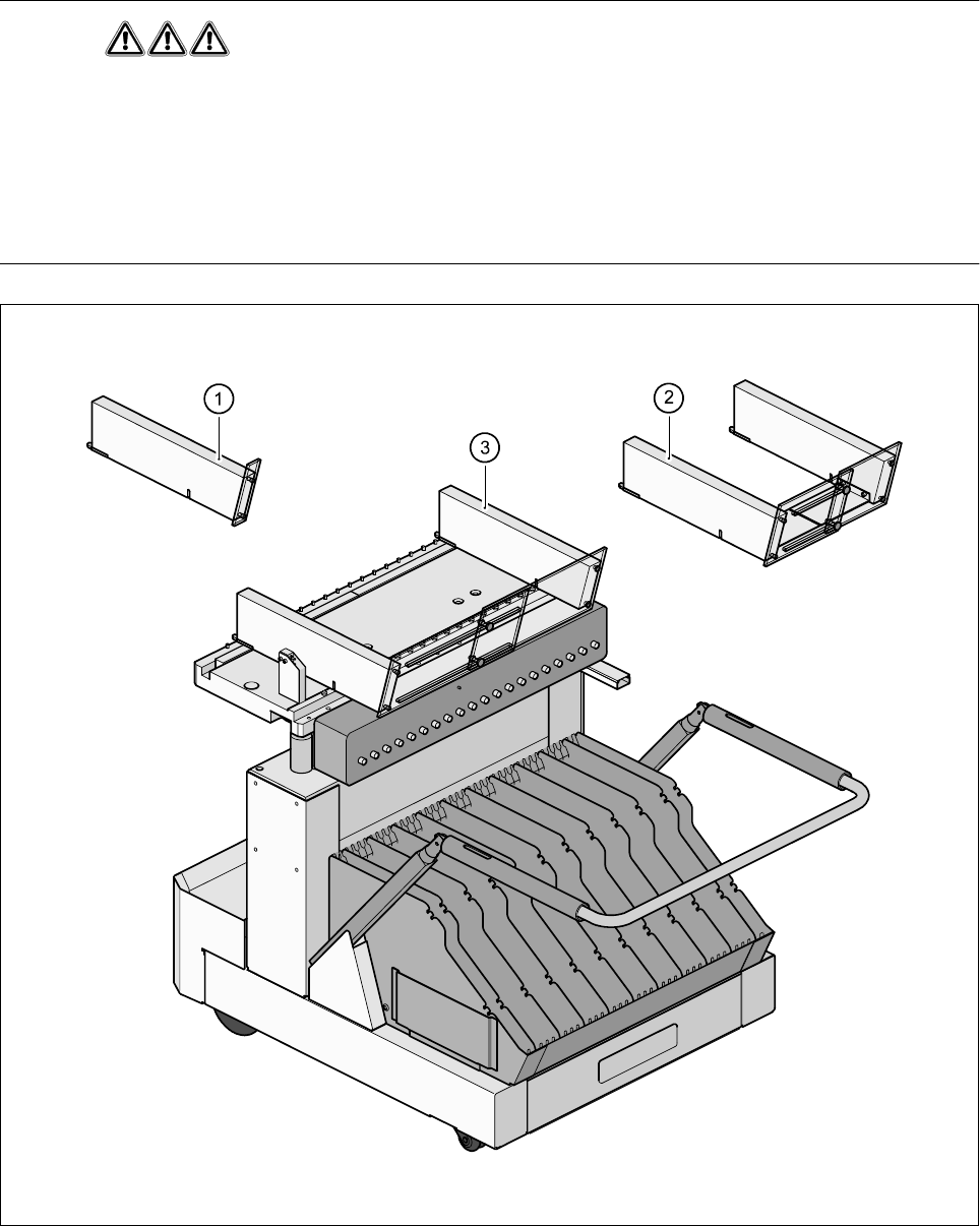
1.2.5 Guard on the component table locations
DANGER
All locations must be equipped with feeders in order to guarantee operational reliability. If there are not enough
conveyors available, a guard ("feeder dummy") must be fitted in place of the conveyor.
The following variants can be used:
Item no. 00116820-01SIPLACE guard for 1 location
Item no. 00116821-01SIPLACE guard for 6-10 locations
Item no. 00116822-01SIPLACE guard for 11-20 locations
Fig. 1.2.6 Guard
- Key to Fig. 1.2.6
1 Guard for 1 location2 Guard for 6-10 locations
3 Guard for 11-20 locations