80S-2080F480F5.pdf - 第68页
1 Operational Safety SIPLACE 80S-20/F4/F5 User Manual 1.2 Safety equipment 05/99 Issue from Software Version SR.405.xx 1 - 30 1.2.5 Guard on the component t able locations DANGER All lo cations must be e quipped wi th fe…
SIPLACE 80S-20/F4/F5 User Manual 1 Operational Safety
05/99 Issue from Software Version SR.405.xx 1.2 Safety equipment
1 - 29
Fig. 1.2.5 SIPLACE 80S-20/F
4
/F
5
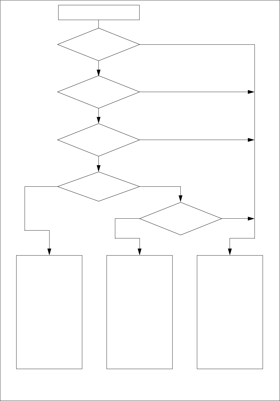
safety circuits
Start button pressed
Emergency stop button
pressed?
Protective cover open ?
Key switch
closed (positionI)?
No
Component table safety
circuit interrupted?
Yes
No
No
Yes
Yes
No
Active
K1 *) Yes
K2 *) Yes
Voltage
y axis 100 V
x axis 100 V
Star axis 100 V
dp axis 30 V
z axis 30 V
Active
PCB conveyor Yes
PCB clamping deviceYes
Width adjustment Yes
PCB stopper Yes
Tape cutter Yes
Yes
Active
K1 *) No
K2 *) Yes
Voltage
y axis 0 V
x axis 0 V
Star axis **) 10 V
dp axis 30 V
z axis 30 V
Active
PCB conveyor Yes
PCB clamping device No
Width adjustment Yes
PCB stopper No
Tape cutter No
Active
K1 *) No
K2 *) No
Voltage
y axis 0 V
x axis 0 V
Star axis **) 10 V
dp axis 30 V
z axis 30 V
Active
PCB conveyor No
PCB clamping device No
Width adjustment No
PCB stopper No
Tape cutter No
*) K1, K2 protective contactor combination
**) The maximum current is limited by a 4.7 Ohm resistor.
Compressed air
min. 5.1 bar?
Yes
No
1 Operational Safety SIPLACE 80S-20/F4/F5 User Manual
1.2 Safety equipment 05/99 Issue from Software Version SR.405.xx
1 - 30
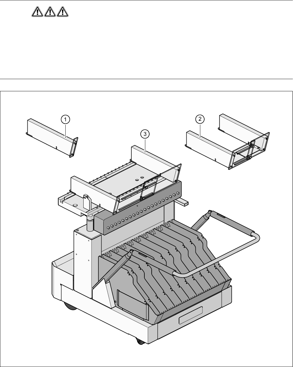
1.2.5 Guard on the component table locations
DANGER
All locations must be equipped with feeders in order to guarantee operational reliability. If there are not enough
conveyors available, a guard ("feeder dummy") must be fitted in place of the conveyor.
The following variants can be used:
Item no. 00116820-01SIPLACE guard for 1 location
Item no. 00116821-01SIPLACE guard for 6-10 locations
Item no. 00116822-01SIPLACE guard for 11-20 locations
Fig. 1.2.6 Guard
- Key to Fig. 1.2.6
1 Guard for 1 location2 Guard for 6-10 locations
3 Guard for 11-20 locations
SIPLACE 80S-20/F4/F5 User Manual 1 Operational Safety
05/99 Issue from Software Version SR.405.xx 1.3 Residual voltages in the servo unit and discharge times when placement system is
switched off
1 - 31
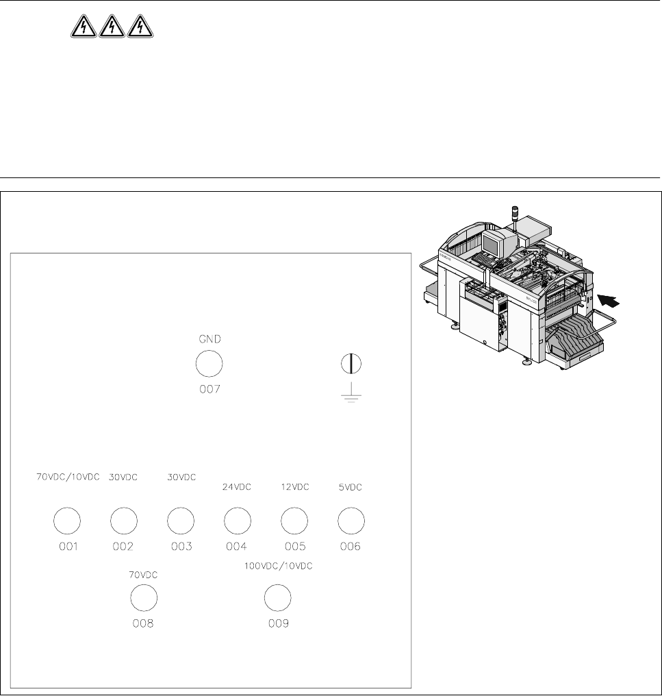
1.3 Residual voltages in the servo unit and discharge
times when placement system is switched off
When the emergency stop button is pressed or the placement system is switched off, the electrolytic capaci-
tors quickly discharge to safe residual voltage levels via switched resistors on the discharge board
(00308443-xx).
The voltages can be tapped off at test sockets 001 - 009 on the voltmeter unit in the servo unit.
DANGER
Automatic placement systems from the SIPLACE family are powered with 3 x 400 V ± 10 %, 50/60 Hz mains
voltage.
This means that parts of the system carry potentially fatal voltages - even when switched off at the main switch.
Death, serious injury or considerable damage may result if these placement systems are handled incorrectly.
Always follow the applicable accident prevention and VDE regulations (particularly VDE 0113).
The guard over the servo unit must ONLY be opened by appropriately qualified and trained personnel.
Fig. 1.3.1 Test sockets on the voltmeter unit in the servo unit
un-
switched
switched
Servo
unit