80S-2080F480F5.pdf - 第692页
11 Station Extensions/Options SIPLACE 80S-20/F4/F5 User Manual 11.10 Twin Conveyor 05/99 I ssue from Software Version SR.405.xx 11 - 76 Fig. 1 1.10.2 General layout view of SIPLACE with twi n conveyor (fixed left side)
SIPLACE 80S-20/F4/F5 User Manual 11 Station Extensions/Options
05/99 Issue from Software Version SR.405.xx 11.10 Twin Conveyor
11 - 75
- Key to Fig. 11.10.1
1 Transport track 1 2 Transport track 2
3 Fixed transport side for transport track 1 4 Fixed transport side for transport track 2
11.10.3 Overview (fixed left side)
The right transport track in the transport direction is designated „Transport 1“ and the left track is designated
„Transport 2“ (see Fig. 11.10.2).
11 Station Extensions/Options SIPLACE 80S-20/F4/F5 User Manual
11.10 Twin Conveyor 05/99 Issue from Software Version SR.405.xx
11 - 76
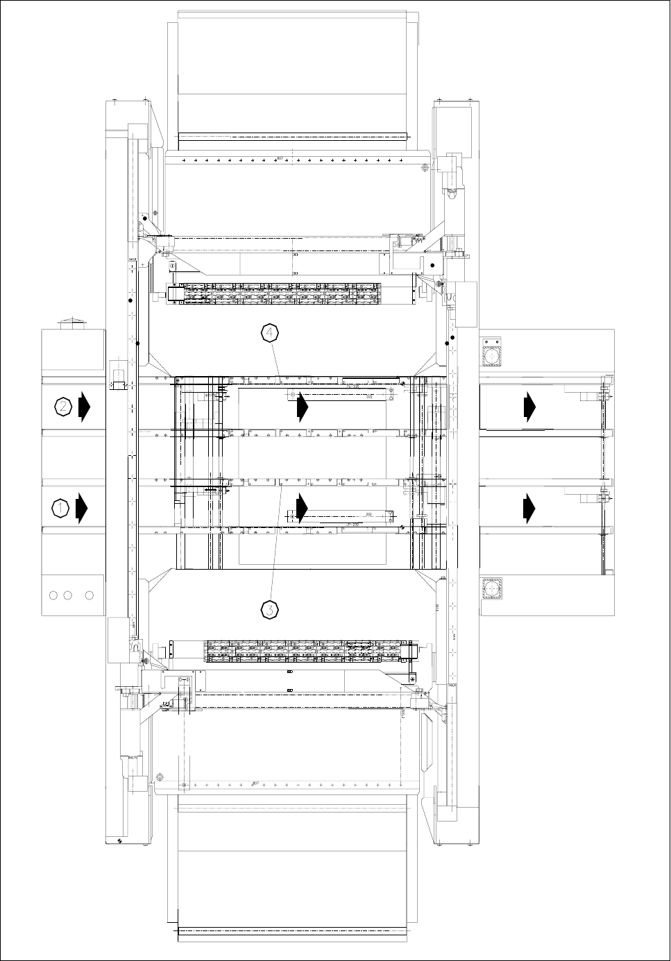
Fig. 11.10.2 General layout view of SIPLACE with twin conveyor (fixed left side)

SIPLACE 80S-20/F4/F5 User Manual 11 Station Extensions/Options
05/99 Issue from Software Version SR.405.xx 11.10 Twin Conveyor
11 - 77
- Key to Fig. 11.10.2
1 Transport track 1 2 Transport track 2
3 Fixed transport side for transport track 1 4 Fixed transport side for transport track 2
11.10.4 Transport Type Asynchronous
11.10.4.1 Description
In asynchronous mode, only one PCB is fitted with components in a transport track, while the other PCB on
the second transport track is moved into the placement position. This halves the transport time, leading to a
considerable increase in output, particularly for PCBs with a low cycle time.
11.10.4.2 Operation
Once the machine has been supplied with job data (cluster, set-up), at each moment during the placement
operation, the PCBs located on the input conveyors are transported into the center conveyor (when the center
conveyor is free). The placement sequence starts as soon as a PCB has been transported onto the free cen-
ter conveyor. The PCBs are fitted with components one after another.
NOTE
The components to be placed and the width of the PCBs on transport tracks 1 and 2 must be identical.
If the placement sequence is interrupted, the transport interface is disabled and placement is completed for
the PCBs still on the center conveyors at this moment.
The transport interface is disabled and enabled simultaneously for both transport tracks.
11.10.5 Transport type synchronous
11.10.5.1 Description
In synchronous mode, two PCBs of the same size are moved simultaneously into the placement position and
must be processed as a common cluster.
This enables the top and bottom of a PCB to be processed on a single line. The time required to transport the
PCBs is reduced since there are always two PCBs being transported at any given time.