80S-2080F480F5.pdf - 第725页
SIPLACE 80S-20/F4/F5 User M anual 17 Nozzle Overview 05/99 Issue from Software Version SR.405.xx 17.1 Nozzle Contour Diagrams 17 - 5 17.1.1.3 Nozzle and Nozzle Contour Fig. 17.1. 3 ’Representation of th e nozzl e contour…
17 Nozzle Overview SIPLACE 80S-20/F4/F5 User Manual
17.1 Nozzle Contour Diagrams 05/99 Issue from Software Version SR.405.xx
17 - 4
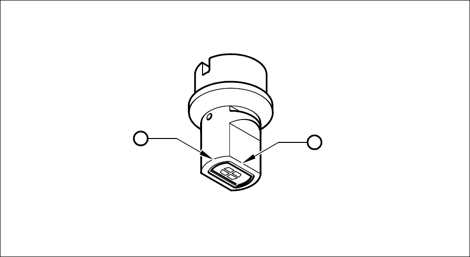
17.1.1.2 Long and Narrow Sides of the Nozzle
For every nozzle type (for example, 7xx) there are two nozzle contour diagrams. One diagram for the long
side and one diagram for the narrow side of the nozzles. In Fig. 17.1.2 the definition of the long and narrow
side of the nozzle is explained.
Fig. 17.1.2 Long and narrow side of the nozzle
- Key to Fig. 17.1.2
1 Long side of the nozzle
2 Narrow side of the nozzle
1
2
SIPLACE 80S-20/F4/F5 User Manual 17 Nozzle Overview
05/99 Issue from Software Version SR.405.xx 17.1 Nozzle Contour Diagrams
17 - 5
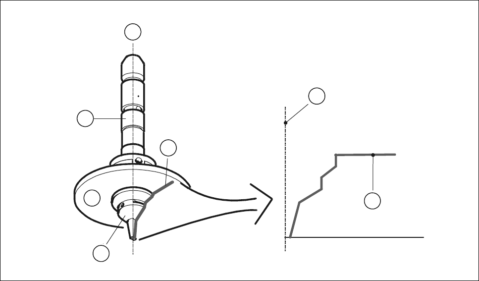
17.1.1.3 Nozzle and Nozzle Contour
Fig. 17.1.3 ’Representation of the nozzle contour’ shows the relation between the nozzle and the nozzle con-
tour. The contour of the nozzle is depicted in the nozzle contour diagram.
Fig. 17.1.3 Representation of the nozzle contour
- Key to Fig. 17.1.3
1 Center of the nozzle
2 Nozzle contour
3Nozzle
4 Encoder disk
5 Segment
1
2
1
2
4
5
3
17 Nozzle Overview SIPLACE 80S-20/F4/F5 User Manual
17.1 Nozzle Contour Diagrams 05/99 Issue from Software Version SR.405.xx
17 - 6
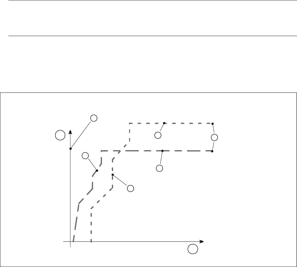
17.1.2 Representation of a Nozzle Contour Diagram
You can obtain the following information from a nozzle contour diagram:
- Placement shadow in [mm]
- Components height difference in [mm]
NOTE
The placement shadow is defined as the distance required between two components when they are
inserted and taking the height difference into account.
A nozzle contour diagram depicts all of the nozzle contours of a nozzle type.
As an example, Fig. 17.1.4 ’Representation of multiple nozzle contour diagrams’ shows two nozzle contours in
one diagram.
Fig. 17.1.4 Representation of multiple nozzle contour diagrams
- Key to Fig. 17.1.4
1 Components height difference in [mm] 2 Placement shadow in [mm]
3 Center of nozzle 4 Nozzle contour of nozzle B
5 Nozzle contour of nozzle A 6 Encoder disk of nozzle B
7 Encoder disk of nozzle A 8 Outside edge of encoder disk
4
1
3
7
6
8
5
2