SIPLACE Vision Customer_en.pdf - 第105页
Component Shapes SIPLACE Vision Robu stness Display New SIPLACE Vision Functions for 605 and 701 Statio n SW S tudent Guide SIPLACE Vision (Customer) Edition 12/2008 EN Component Shapes 105 5-6: Brightness tests With the…
Component Shapes
New SIPLACE Vision Functions for 605 and 701 Station SW SIPLACE Vision Robustness Display
Student Guide SIPLACE Vision (Customer)
Component Shapes Edition 12/2008 EN
104
5.4.2.3 Brightness Modification
To allow a comparison between the original brightness and the maximum possible modification, at which
it is still possible to recognize the CHIP component example, the cursor is placed on the same shadow
point at the end of the left lead in the camera picture of the C&P20 camera (SST 23).
The most extreme illumination conditions are compared with the corresponding original image.
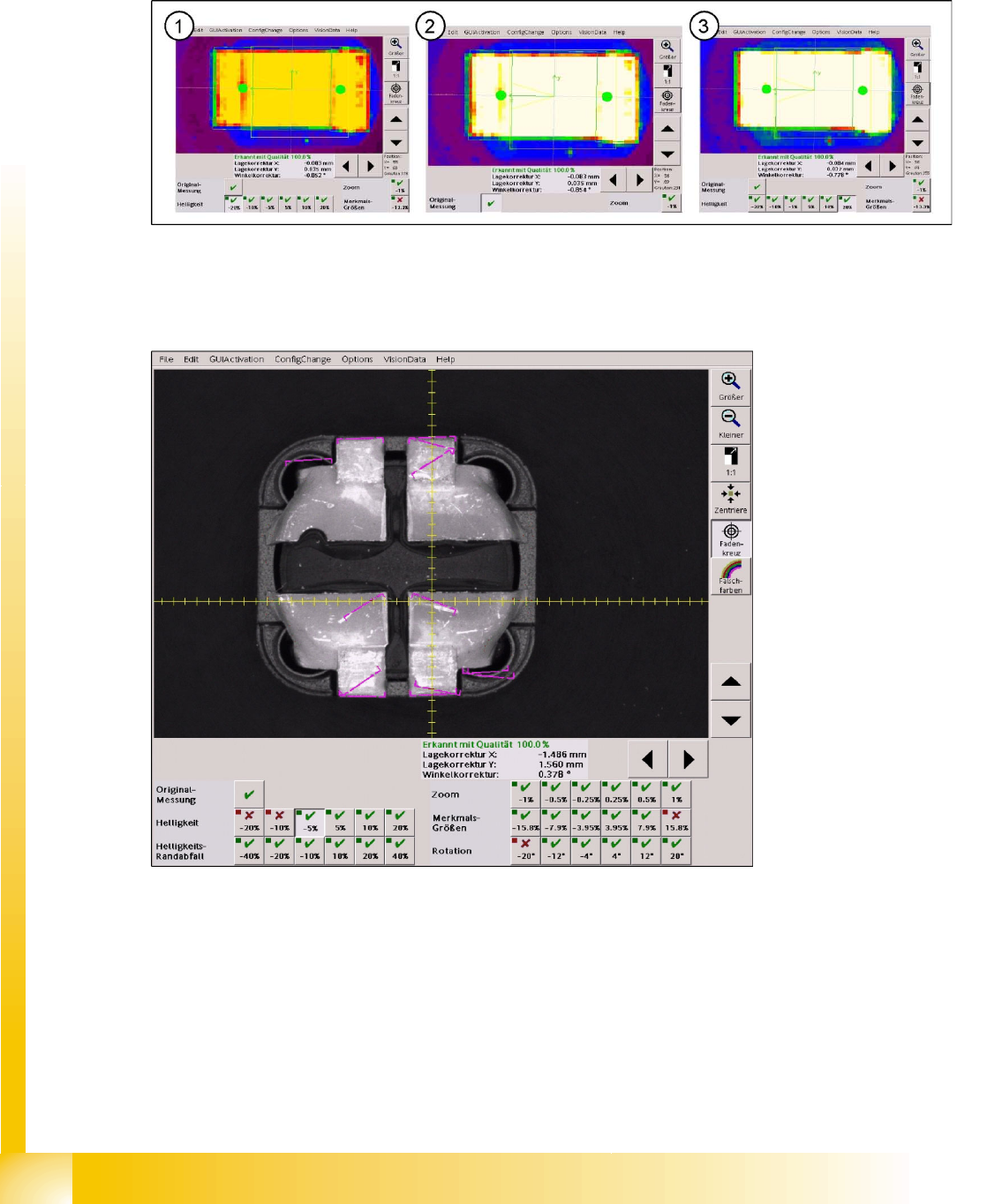
5-4: (1) Brightness value -20% at 178 – (2) Original illiumination at 230 – (3) Overexposed at +20% … at 255
The illumination values of the original image were set to default values in all 5 illumination levels (80/80/
80/120/180). If the illumination is too low, a brightness problem occurs in the robustness tests with
reduced illumination.
5-5: Brightness value reduced by 5%
At this brightness value, which is reduced by 5% with respect to the original picture, the leads can still
be found without rotation at the lead ends. All other measurement steps including the inspection succeed
despite the reduced brightness and the very matt lead surface.
Below, all measurement steps of the brightness values, for which the measurement fails, are shown:
Component Shapes
SIPLACE Vision Robustness Display New SIPLACE Vision Functions for 605 and 701 Station SW
Student Guide SIPLACE Vision (Customer)
Edition 12/2008 EN Component Shapes
105
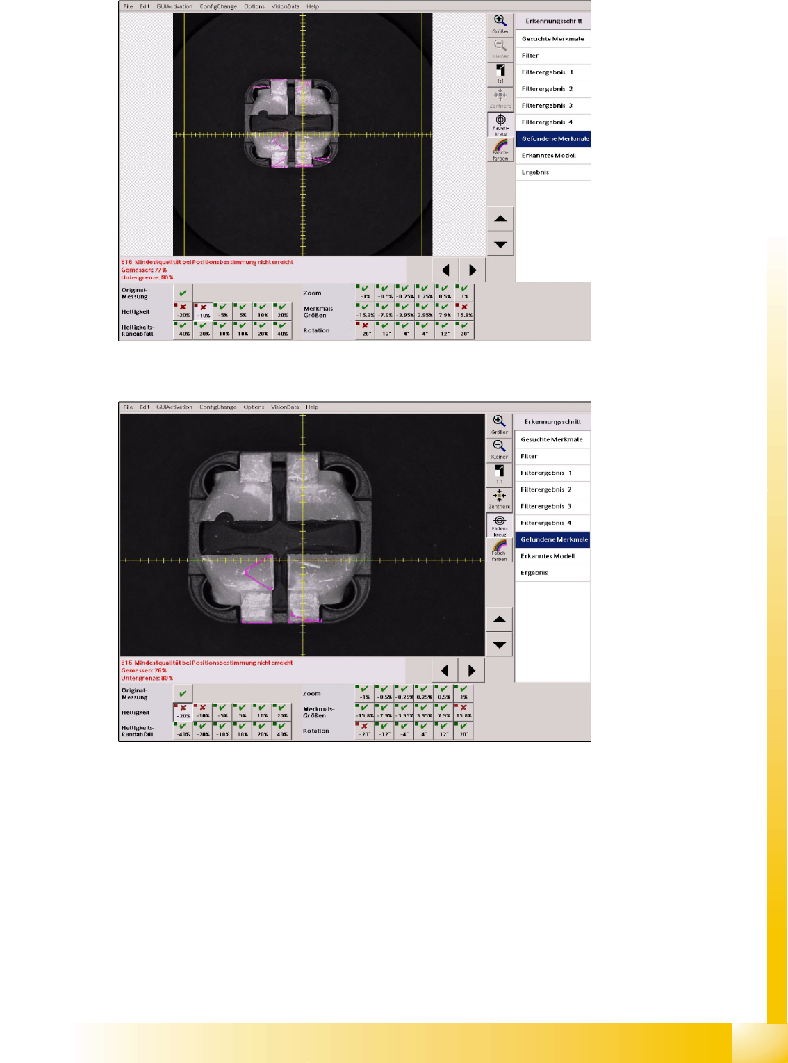
5-6: Brightness tests
With the brightness reduced by 10% the leads only produce a gray value of 130 (red green) at the edges.
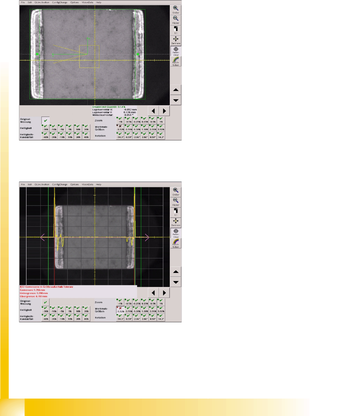
5-7: Brightness tests
With the brightness reduced by 20% the leads at other edge surfaces only produce gray values between
100 and 120 (green).
For this reason the filter edges of the leads are not found in a horizontal position as in the programmed
geometry. No model will be recognized at the position concerned, none of the inspection steps will be
performed or shown accordingly in the menu window.
5.4.2.4 Shading at the Image Border
This function was carried out with component of 5.6 x 5.1 mm (2220) in size at a C&P20 camera. Thus
a component border with almost the specified borders of the camera with an FoV of 8.4 x 8.4 mm results.
(The reticle shows a graduation of 0.1 mm.)
Component Shapes
New SIPLACE Vision Functions for 605 and 701 Station SW SIPLACE Vision Robustness Display
Student Guide SIPLACE Vision (Customer)
Component Shapes Edition 12/2008 EN
106
5.4.2.5 Scale or FeatureSize
For CHIP and MELF components shape and feature size values are directly connected. The shape
widths correspond to the leg widths, the shape lengths in X direction determine the offset for leg groups
at a given leg length. For this reason both checks are discussed together.
If the faulty measurement result is opened, each measurement step that could fail in this robustness test
can be selected.
The correction of the X dimension from 5.8 mm to 5.7 mm has the effect that the reduced component
charge will be detected because it is inside the 0.4 mm size tolerance after the correction.
5-8: Original component shape size "measurement result"
The mechanical dimension in Y direction (vertical)
was correctly programmed, which can be
recognized in the congruence of the programmed
outline and the shape edges of the component.
In contrast, the X dimension is a bit too large. But
this has no unfavorable effect on the
measurement result.
A smaller component, however, would be rejected
because of a size error.
5-9: Reduced component shape size X dimension check
As can be seen in the X dimension inspection
step, the recognition of the shape edge for
reduced component dimensions fails on the right
side of the component. The red line shows the
recognized shape edge which is located outside
the position tolerances marked with a green line.