SIPLACE Vision Customer_en.pdf - 第117页
Component Shapes SIPLACE Vision Flux Inspection – only in 605 SW New SIPLACE Vision Functions for 702 Station SW S tudent Guide SIPLACE Vision (Customer) Edition 12/2008 EN Component Shapes 11 7 X A constantly sufficient…
Component Shapes
New SIPLACE Vision Functions for 605 and 701 Station SW SIPLACE Vision Flux Inspection – only in 605 SW
Student Guide SIPLACE Vision (Customer)
Component Shapes Edition 12/2008 EN
116
X In a next step check the parameter settings for an undipped component. Switch back to the form
editor and re-activate dipping.
X Get the component and switch to the
Monitoring
Vision view.
If the position of the component cannot be detected because the component is too dark, the
illumination must be brightened up until the position can be reliably determined. Please brighten up
only to such an extent, that is absolutely necessary to detect the component.
X Select the
Flux diagram
view (see above).
In this view you have to check if the selected areas really show the greatest modifications through
dipping. Again, the differences between the characteristics should be as small as possible. The
threshold should be above all characteristics now (if they were set as described).
If this is not the case, either the parameterization has to be checked or it has to be checked if the flux
or solder paste is suitable.
If the threshold is comfortably above the characteristics it can be reduced to a value that enables
insufficiently coated balls to be detected earlier. The selected threshold depends on the conditions
and the process requirements at the customer's site.
X If the correct parameterization has been found, save it.
X Based on the existing patterns the distance of the characteristics between dipped and un-dipped
component should be at least 20 pixel for the contrast procedure and at least 40 for the brightness
procedure.
X The values for the characteristics and their differences between dipped and un-dipped depend on:
the properties of the flux, the surface properties of the balls, the height of the flux or solder paste in
the dipping unit, the dipping time, the selected analysis areas (via DonutInner and DonutOuter) and
the selected illumination.
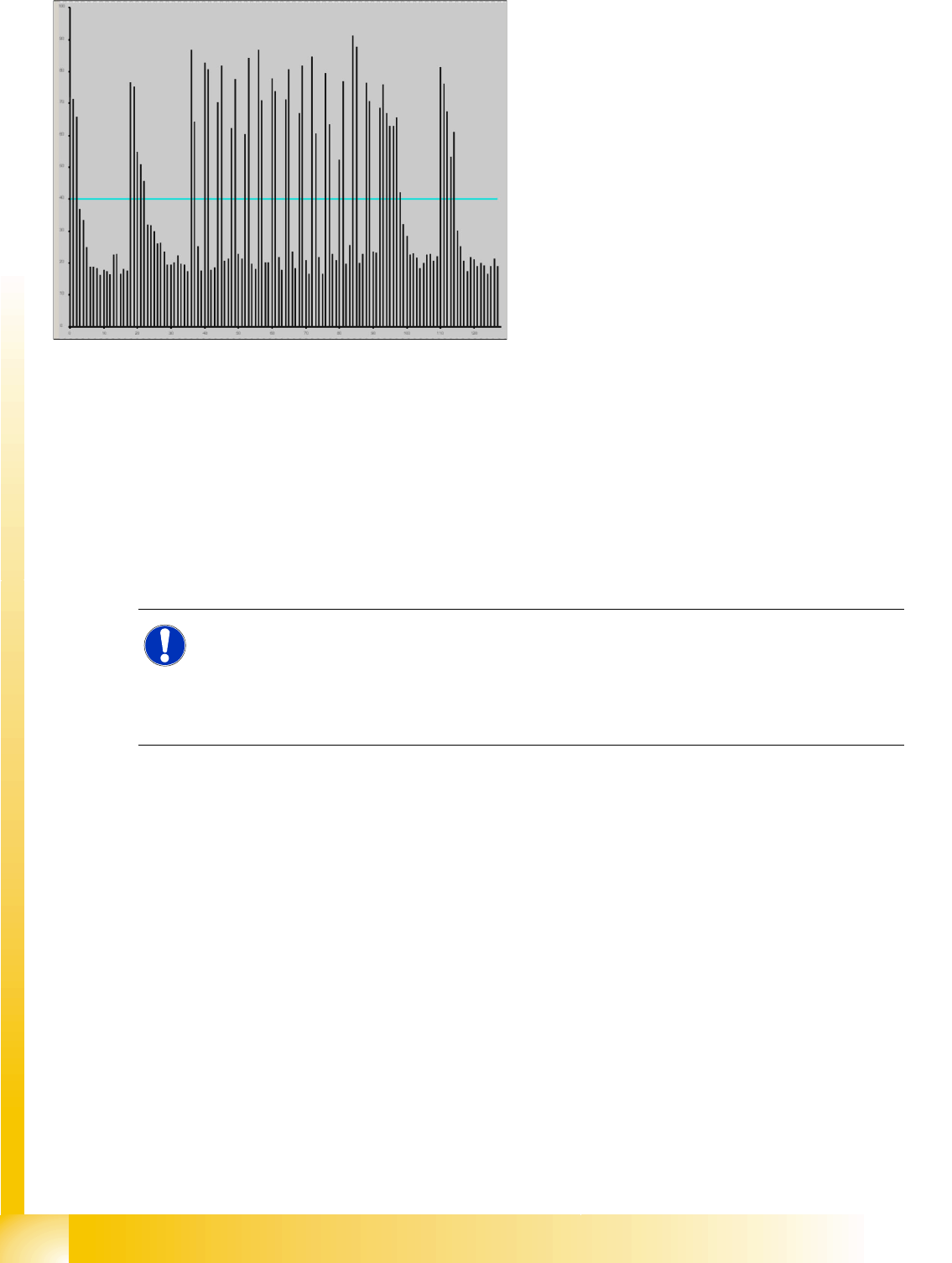
5-20: Flux diagram
X Deactivate dipping in order to calculate the
characteristics for un-dipped balls.
Get the component and switch to the
Monitoring
Vision view. Select the
Flux
diagram
view (see the figure).
X This diagram shows the characteristics of all
balls and the differentiation threshold.
The selected detection procedure and the
parameterization of the evaluation areas
(DonutOuter and DonutInner) have an effect
on the characteristics.
It is the aim to find a setting that includes the
areas with the greatest modifications as a
result of the dipping. At the same time the
differences between the characteristics should
be as small as possible.
X Set the threshold to a value that is a bit lower
than all characteristics of the balls. Thus all
balls will be characterized as insufficiently
coated.
NOTE:
If the illumination is too bright the differentiation becomes worse because pixel on un-coated
balls may be overexposed. Overexposed pixel always have a gray value of 255 independent of
the extent of the overexposure. If the previously dark pixel also become very bright after
brightening the illumination, e. g. if a gray value of 40 augments to 200, the differentiation gets
correspondingly worse.

Component Shapes
SIPLACE Vision Flux Inspection – only in 605 SW New SIPLACE Vision Functions for 702 Station SW
Student Guide SIPLACE Vision (Customer)
Edition 12/2008 EN Component Shapes
117
X A constantly sufficient differentiation can not be guaranteed.
For this reason the influencing parameters always have to be analyzed and matched together with
the customer in advance.
5.5 New SIPLACE Vision Functions for 702 Station SW
A range of new functions have been introduced with SIPLACE Vision SW 4.0.1 4 for station SW 702.
These functions were not available in 605.01 or 701.0x.
Require separate group description:
this function can now be enabled from the SIPLACE Vision teach interface. Programming which uses
special SIPLACE Vision parameters will automatically enable this separation of the group
description.
Changed face down recognition:
The face down recognition has been extended to support more component shape types. It now also
includes a lead length inspection.
Lead recognition for Gullwing and Wraparound:
These lead types are now checked for the lead width.
You can also check the linearity of the lead measuring edges within a certain group.
Rectangle:
There is now a new rectangular feature for optical recognition of Nonstandard.
Fiducial recognition:
The tolerance of the bar width in cross or double cross fiducials has been increased from 20% to
30%. Other fiducial tolerances remain at a maximum of 20 % for accuracy purposes.
The flux inspection described for 605 and 701 remains in the 702 SW.
For a detailed description see above.
ATTENTION:
The procedure does not return a value for the layer thickness of the flux on the coated ball.
Component Shapes
New SIPLACE Vision Functions for 702 Station SW Face Down Recognition
Student Guide SIPLACE Vision (Customer)
Component Shapes Edition 12/2008 EN
118
5.5.1 Face Down Recognition
The face down recognition of components has been extended from (only) CHIP to now also support
BareDie, molded, SOxx, QFP, SOT, DPACK, Socket, Connector, Nonstandard, (on component shapes
with wraparound and gullwing leads). It is not used for ECV and MELF!
The measurement function can be enabled separately in the geometry program section "
Special
Measurement Options
".
The size of the face down recognition field (FaceDown Region Of Interest) can now be individually
specified.
This face down recognition has been extended to include a lead length measurement for CHIP and
molded component shapes. This enables you to differentiate between component images with the same
dimensions or to use another face down recognition run.
The measurement function for checking the length can be separately enabled in the geometry program
section "
Special Measurement Options
".
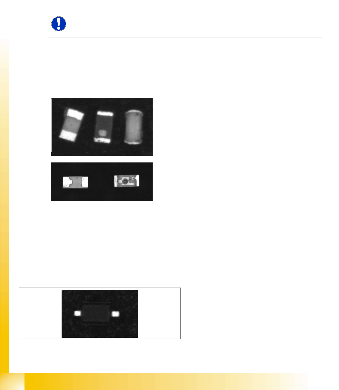
The components on the left in each of the following diagrams need to be placed.
5.5.2 Lead Measurement
Lead width inspection
The lead width inspection has now been extended from a size determination for lead recognition filters
to an active width measurement function.
This measuring function is switched on in the geometry program area
"Special Measurement Options".
Application: If a SO2 (SOD323) is taken up sideways on the nozzle, this was previously only recognized
if the lead filters failed.
NOTE:
Please note that these surface structures are NOT usually specified in the manufacturer's data.
This means that the manufacturer could alter this feature in any production batch.
With the new function (SV 4.0.1), the pin width is
measured actively during the inspection and must
match the programmed nominal width +/- width
tolerance factor (as shown, for example, in the
diagram on the left).