SIPLACE Vision Customer_en.pdf - 第12页
Introduction Component Centering Nozzle Scan S tudent Guide SIPLACE V ision (Customer) Introduction Edition 12/2008 EN 12 3.2 Component Centering Optical component centering targets Determination of the exact componen …

Introduction
Board Centering and Inkspot Recognition
Student Guide SIPLACE Vision (Customer)
Edition 12/2008 EN Introduction
11
3Introduction
SIPLACE Vision is the new image processing system for analyzing optical centering (CO and board
centering, feeder position) and other test (inkspots, nozzle scanning). Machines using the older ICOS
system can also be operated with the same SIPLACE Pro CS database.
3.1 Board Centering and Inkspot Recognition
SIPLACE Vision provides a board centering system with nine synthetic fiducial types. Users will normally
find a suitable fiducial type among these. Simply specify the required fiducial type, contrast and
dimensions (size and tolerances) to begin the teaching procedure at the station. There is then no need
for further fiducial teaching in this case.
A fiducial wizard for simple, guided fiducial teaching has been available since SW version 604.
However, if the fiducial to be used for the board does not correspond with any of the predefined synthetic
fiducial types, users will need to teach the system an additional fiducial template (e.g. triangle or PCB
track structure).
Optical board centering targets
Determination of exact board position and board distortion.
Recognition of boards with bad fiducial quality - these are then sorted out and ignored by the
placement process.
Background: Bad fiducial quality usually results in a poor pad image, since these are produced in the
same production step. The corresponding boards may then show electrical faults.
Inkspot recognition
Inkspot recognition enables users to differentiate between two cases:
Good: Board or panel placement will be performed.
Bad: Board or panel placement will not be performed.
For rapid inkspot recognition, users need to define a synthetic good inkspot.
Alternatively, users could teach one good inkspot and one bad inkspot.
Introduction
Component Centering Nozzle Scan
Student Guide SIPLACE Vision (Customer)
Introduction Edition 12/2008 EN
12
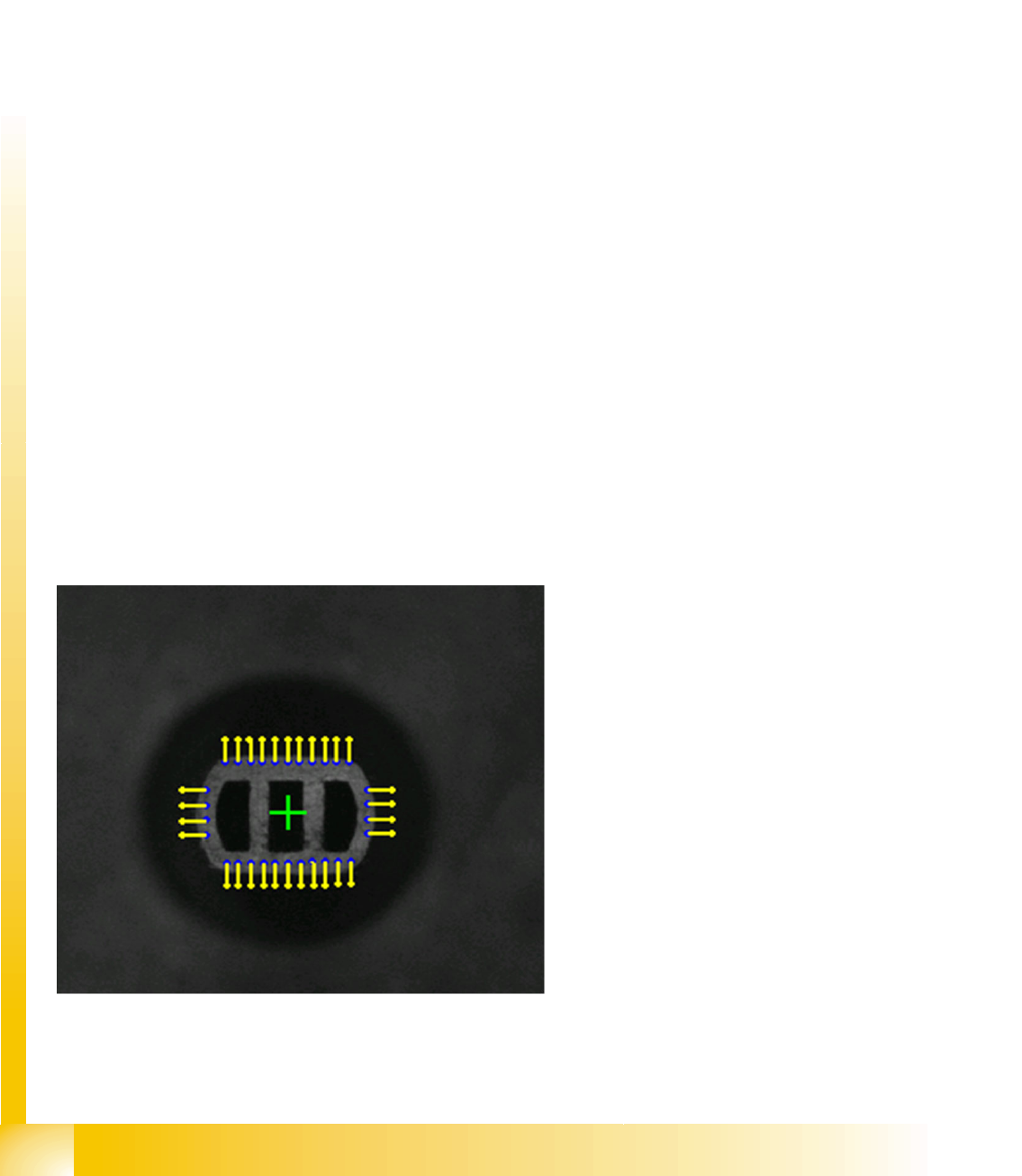
3.2 Component Centering
Optical component centering targets
Determination of the exact component position.
Optical inspection of the components, in order to sort out and reject poor quality components from
the placement process. This applies to components which are outside the tolerance range or which
have bent leads. For the component shape (CS) teaching or test procedure, this means that
the error situation needs to be simulated and reliably recognized by the Vision system.
Placement of the components recognized as good in the best possible placement position (best X/
Y position and optimum placement angle).
When you assign the component to one of the basic component shapes in SIPLACE Vision, the system
sets the optimum analyzing algorithm and type-specific illumination for that component. To achieve
reliable component recognition, enter the geometric description of the component shape in SIPLACE
Pro, as specified in the data sheet or teach the component shape with the camera at the station (since
SR/MC 603.01 this is also possible with a CS wizard tool).
Should a problem arise, the setter will be asked to check the component shape geometry, in order to
reestablish the reliability of the component recognition function.
Should a real problem arise, you can generate an analysis/results log for the fiducials and component
shapes. This log contains the relevant fiducial or component shape data, including the camera images
recorded.
Send this log to the SIEMENS Service team for advice and to improve your data results.
3.3 Machine Tests with Cameras
SIPLACE Vision can also be used to check the machine state. The following functions are currently
enabled here:
3.3.1 Nozzle Scan
Nozzles for small components are optically
scanned for contaminants during the
reference run for the C&P head, after
placement of the first board and after 350 head
cycles (at the end of the board), respectively.
– If a defect is detected after evaluation of
the camera image, the system will report
Nozzle dirty here.
– If the vacuum duct is contaminated inside,
at the nozzle tip, the vacuum
measurement test will recognize this and
report Vacuum channel polluted.
The adjacent diagram shows outline recognition of
a normal nozzle tip.

Introduction
Feeder Position Recognition Camera Overview
Student Guide SIPLACE Vision (Customer)
Edition 12/2008 EN Introduction
13
3.3.2 Feeder Position Recognition
SIPLACE Vision performs feeder position recognition directly before placement begins. The procedure
measures various feeder-specific system fiducials or geometric data for tape pockets, to determine the
actual component pickup position for the respective feeder track.
Before placement begins for a new job, the new X-series component tables are measured with the
PCB camera, by optically centering two fiducials per location.
The two table fiducials are also measured for these tables. These values are used to calculate the
pickup position of each feeder.
When using components which are smaller than 1.0x0.5 mm (0402), the system measures the
empty tape pockets for the respective track, directly before the pickup position.
3.4 Camera Overview
Overview of component cameras in placement head
Parameters C&P20
Camera
C&P12
Camera
Standard
C&P12
camera
0603 mm
(0201) ‚HR’
C&P12
camera
0402 mm
(01005)
C&P6
Camera
For placement head C&P20 DLM2 12 DLM2 12 HR DLM2 12
01005 option
(D series)
DLM2
C&P6
SST 23 28 29 38 29
Resolution [µm] 17 50 26 18 26
Field of [mm²] 8 x 8 24.5 x 24.5 24.5 x 24.5 20 x 20 32 x 32
Min. CO size [mm²] 0.2 x 0.2 0.5 x 0.5 0.3 x 0.3 0.2 x 0.2 0.5 x 0.5
Suitable for min. CHIP size 01005 0402 0201 01005 0402
Max. CO size [mm²] 6 x 6 18.7 x 18.7 18.7 x 18.7 16 x 16 27 x 27
Min. lead pitch [µm] 300 400 300 100 300
Min lead width [µm] 100 200 150 100 150
Min. ball pitch [µm] 400 450 250 250 300 (350 if
component >
18 mm)
Min. ball [µm] 200 250 140 140 150 (200 if
component >
18 mm)
Illumination levels
(programmable)
5
(5)
4
(5)
4
(5)
4
(5)
4
(6)
Teaching /centering the
component presentation
angle
In 0° / 90°
steps
/ placement
angle
In 0° / 90°
steps
/ pickup angle
In 0° / 90°
steps
/ pickup angle
In 0° / 90°
steps
/ pickup angle
In 0° / 90°
steps
/ pickup angle