SIPLACE Vision Customer_en.pdf - 第132页
SIPLACE Vision - Teaching Fiducials Fiducial shapes Synthetic Fiducials fo r Position Recognition Applications S tudent Guide SIPLACE V ision (Customer) SIPLACE Vision - T eaching Fiducials Edition 12/2008 EN 132 6.2 Fid…
SIPLACE Vision - Teaching Fiducials
Placement Position Recognition What are Fiducials?
Student Guide SIPLACE Vision (Customer)
Edition 12/2008 EN SIPLACE Vision - Teaching Fiducials
131
6.1.2 Placement Position Recognition
A fiducial on a PCB can also be used for exact measurement of a placement position. The position
coordinates relate to the Overall PCB zero point or the Panel zero point and not to the placement
position to be measured. The fiducials can either be positioned diagonally on the corners of the
placement layout at the placement position or in the center. The measurement results and centering
steps for PCB position recognition or placement position determination do not differ from one another!
6.1.3 Good/Bad Board Recognition of So-Called Inkspot Recognition
Boards with multiple panels often need to have panels with a defect or ones for prior production omitted,
so that expensive components are not placed where it is not necessary.
In contrast to the two previous applications, explained above, this procedure does not involve
determining position coordinates during the fiducial measurement but, instead, just the relevant optical
impression, brightness or contrast.
To save time, a so-called "global inkspot" has been created.
When recognized as OK, this global inkspot defines that all panels are OK and suitable for
placement.
If recognized as bad, this global inkspot defines that at least one panel is NOT OK and is therefore
to be omitted after the relevant fiducials have been scanned.
The fiducial for good/bad panel recognition is often also on the overall PCB. This saves placement space
on the individual panel, although it does make work more difficult for the programmer and line operator.
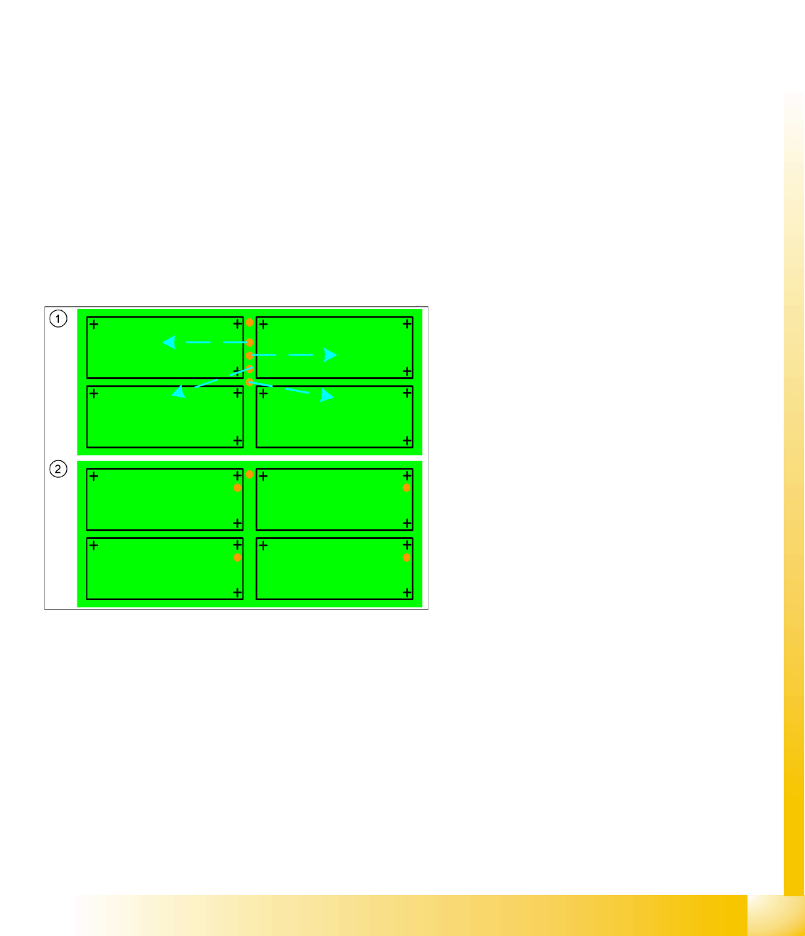
Legend
1. Inkspot fiducials for panels on the entire PCB
frame or edge
This arrangement of inkspots requires
individual programming of each panel!
It is also essential that the operator knows
which inkspot is assigned to each panel.
2. Inkspot fiducials in the panels
In the standard arrangement of inkspot
fiducials in the panel , this is "automatically"
clear due to the duplicate arrangement in the
panel.

SIPLACE Vision - Teaching Fiducials
Fiducial shapes Synthetic Fiducials for Position Recognition Applications
Student Guide SIPLACE Vision (Customer)
SIPLACE Vision - Teaching Fiducials Edition 12/2008 EN
132
6.2 Fiducial shapes
One fiducial shape can be used for all the applications described above. However, since one application
uses position measuring algorithms and the other application (inkspot) does not, this shape will need to
be trained twice.
This means:
A fiducial shape is trained for the fiducial library in SIPLACE Pro and can then be called up for PCB
programming and supplemented with coordinates and the respective position measurement
application.
A fiducial shape is trained for the fiducial library in SIPLACE Pro and can then be assigned
coordinates, so that the gantry can position the camera for good/bad recognition.
See also the programming guides in SIPLACE Pro x.x
6.2.1 Synthetic Fiducials for Position Recognition Applications
Fiducials which have shapes which are symmetrically arranged around a center point can be easily
described and recognized.
Synthetic fiducials are more exact than sample fiducials, as the inaccuracies of the so-called "gold
sample", to be learnt, do not apply.
The following parameters are sufficient for the description of these fiducials:
The shape (cross, circle, ring, rectangle (special shape: square), rectangular ring, 45° square
(diamond), doublecross)
The size or other dimensions such as bar width
The contrast to the background (fiducial bright or dark)
Using these specifications, the outer edges can be determined and taken for rough (coarse) and fine
structure recognition.
Since SR/MC 603.xx, synthetic fiducials can also be trained with a fiducial wizard.
SIPLACE Vision - Teaching Fiducials
Synthetic Fiducials for Position Recognition Applications Fiducial shapes
Student Guide SIPLACE Vision (Customer)
Edition 12/2008 EN SIPLACE Vision - Teaching Fiducials
133
6.2.1.1 Programming the Fiducial
Fiducial recognition is based on a correct description of the geometry, which is why the geometry
programming window is described here.
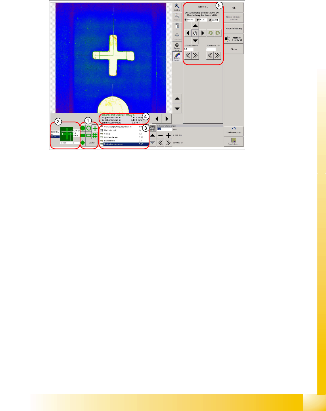
6-4: Programming geometry – teaching
Legend
1. Selection of geometry for synthetic fiducials or pattern programming
2. Quick access to the dimension parameters of the fiducial geometry and to the contrast to the PCB
background
3. Table of fiducial dimension parameters
4. Result of fiducial recognition
The X/Y deviation to the camera center point is given for the correctly recognized fiducial
During teaching/testing, a fiducial angle (exception: circular fiducials 0.0°) to the camera coordinates
is specified. However, this is not processed further by the MC during placement measurement.
5. Programming drawing displacement or centering step selection area
The fiducial is saved once the notifications window displayed when you exit the teaching menu has
been acknowledged.
A smaller size can be programmed for structures such as the cross-shaped fiducial, since the fiducial
shape remains the same and leads to the same fiducial center if parts of the cross bars are cut off. The
image pairs, 16 per cross bar, are set closer together in smaller cross-shaped fiducial sizes to ensure
that the edges are recognized reliably.
In fiducials taking up more space, such as circles, the fiducial background of the entire shape must be
recognizable. If this is not the case, it will not be possible to recognize the fiducial shape and the fiducial
center. This means that the evaluation area needs to be larger than the fiducial area.