SIPLACE Vision Customer_en.pdf - 第136页
SIPLACE Vision - Teaching Fiducials Fiducial shapes Synthetic Fiducials fo r Position Recognition Applications S tudent Guide SIPLACE V ision (Customer) SIPLACE Vision - T eaching Fiducials Edition 12/2008 EN 136 75% (st…
SIPLACE Vision - Teaching Fiducials
Synthetic Fiducials for Position Recognition Applications Fiducial shapes
Student Guide SIPLACE Vision (Customer)
Edition 12/2008 EN SIPLACE Vision - Teaching Fiducials
135
6.2.1.3 Recognition of Synthetic Fiducials
One of the 3 position recognition fiducials should have at least the maximum position correction
(otherwise the error
ROI (Region of Interest) too small
will be issued).
The other two fiducials can have limited presentation tolerances:
max. position correction = (FOV – fiducial size inc. size tolerance) / 2
e.g. X = (5.7 mm – 2.1 mm) / 2 = 1.8 mm
During placement, the position fiducials are approached in the order of their search field size.
If the position correction of the fiducial has been restricted in SIPLACE Pro, this value will be shown as
the correction value in the "Position correction X/Y" lines.
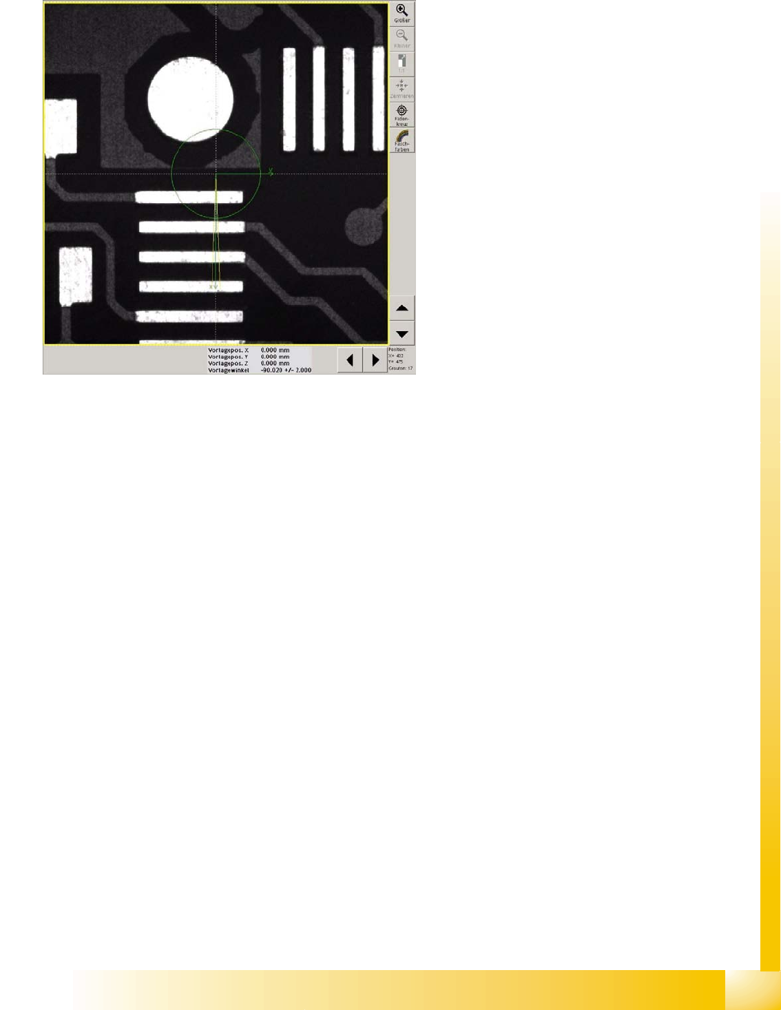
6-5: Position correction
The centering step camera image shows the
unedited camera image resulting from the current
PCB position and PCB camera at the theoretical
fiducial position in the machine.
The centering step "position correction" shows the
fiducial shape and size in the PCB camera center,
with the permitted angle correction of 2°.
The angle shows the assembly position of the
camera at the gantry and the PCB camera
calibration angle.
If a position correction is programmed which
corresponds to the whole PCB camera field of
vision (5.7x5.7mm), the yellow frame of the search
field will show the relevant extract from the whole
image.
When the position correction is the same as the
whole camera field of vision, no X/Y position
correction will be shown in the results line.
SIPLACE Vision - Teaching Fiducials
Fiducial shapes Synthetic Fiducials for Position Recognition Applications
Student Guide SIPLACE Vision (Customer)
SIPLACE Vision - Teaching Fiducials Edition 12/2008 EN
136
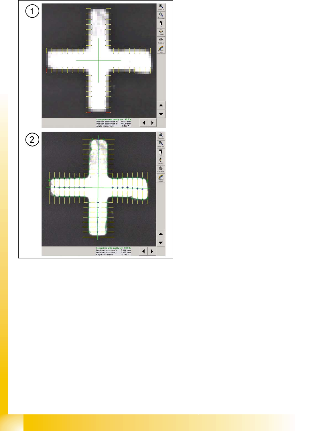
75% (standard) of the point pairs (edge search positions) need to be recognized, so that the fiducial
measurement results are shown at the bottom (middle) of the image (see also algorithm settings).
The tolerance values for the bar width (max. 20%) alter the point pair pitch for the precentering of the
cross fiducial and therefore also affect the marking lines for the fine edge search.
6-6: Fiducial centering steps with standard algorithm settings
Legend
1. Subsampling shows the 16 (standard in
algorithm setting) point pairs of the cross bars.
One of the pixels (marked blue) in the pair
must reach the bright fiducial foreground and
one (yellow) must reach the dark background,
before the point pair connection is marked
yellow and can be used for precentering the
fiducial position. Positions which are marked
red will be rejected.
2. The Fine search examines the brightness
transitions along the lines connecting the 16
point pairs, determined in the rough search, to
determine the exact fiducial center point. The
green crosses mark the position of greatest
gradient change. The blue dot marks this
position if the distance is within the bar width
tolerance range (fine structure).
The fiducial edge positions are calculated and
used to accurately interpolate the fiducial
center.
SIPLACE Vision - Teaching Fiducials
Synthetic Fiducials for Position Recognition Applications Fiducial shapes
Student Guide SIPLACE Vision (Customer)
Edition 12/2008 EN SIPLACE Vision - Teaching Fiducials
137
6.2.1.4 Illuminating Fiducials with the Different PCB Cameras
2 camera systems with different illumination technology are available for fiducial recognition.
Camera data SST34 and 24:
– Field of vision 494x494 mm (494x494 pixels)
– Max. fiducial size 3x3 mm
– Resolution~12 µm/pixels
The standard PCB camera SST34 supports the following illumination options:
– Red LEDs, which support diffuse illumination of the structure, through opaque or milky glass.
This type of illumination can be selected on its own.
– Red LEDs, which support direct illumination of the structure, through an opening in the opaque
or milky glass. This can only be selected in combination with diffuse illumination.
– Direct illumination with blue LEDs as ring arrangement - suitable for white ceramic PCBs with
metallic fiducial shapes.
The multicolor illumination camera SST24 supports the following illumination options:
– Infrared and white LEDs, which support diffuse illumination of the structure, through opaque or
milky glass. These types of illumination can be selected on their own.
– Infrared and white LEDs, which support direct illumination of the structure, through an opening
in the opaque or milky glass. This can only be selected in combination with diffuse illumination.
– Direct illumination with blue LEDs as ring arrangement - suitable for white ceramic PCBs with
metallic fiducial shapes.
– This camera is only available as an option for X machines.
The intensity of each illumination type can be set to between 0 and 255. The illumination colors can not
be combined with one another.
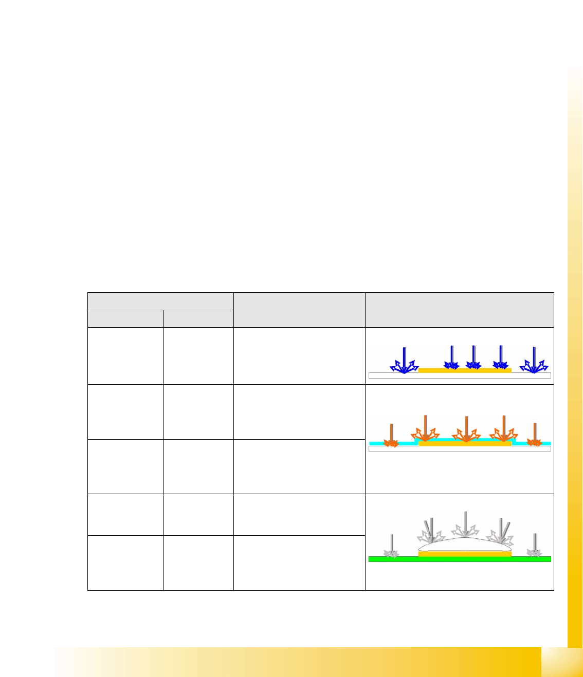
Illumination type/color PCB material Example
SST24 SST34
Blue Blue For recognition of gold or silver
colored fiducials on white
(ceramic) material
e.g. gold on ceramic
Infrared (IR)
diffuse
Red, diffuse For recognition of fiducials
under soldering paste and of
matt coated fiducials, plus
fiducials on glass sheets.
IR penetrates soldering paste and illuminates
covered structures.
IR steep is
always
combined with
diffuse
Red steep is
always
combined with
diffuse
For recognition of shiny coated
fiducials
White, diffuse Red, diffuse For recognition of matt
fiducials on any PCB material
and PCB surface.
Fiducials tin-plated with hot air
White steep is
always
combined with
diffuse
Red steep is
always
combined with
diffuse
For recognition of fiducials with
shiny surfaces