SIPLACE Vision Customer_en.pdf - 第138页
SIPLACE Vision - Teaching Fiducials Fiducial shapes Synthetic Fiducials fo r Position Recognition Applications S tudent Guide SIPLACE V ision (Customer) SIPLACE Vision - T eaching Fiducials Edition 12/2008 EN 138 6.2.1.5…
SIPLACE Vision - Teaching Fiducials
Synthetic Fiducials for Position Recognition Applications Fiducial shapes
Student Guide SIPLACE Vision (Customer)
Edition 12/2008 EN SIPLACE Vision - Teaching Fiducials
137
6.2.1.4 Illuminating Fiducials with the Different PCB Cameras
2 camera systems with different illumination technology are available for fiducial recognition.
Camera data SST34 and 24:
– Field of vision 494x494 mm (494x494 pixels)
– Max. fiducial size 3x3 mm
– Resolution~12 µm/pixels
The standard PCB camera SST34 supports the following illumination options:
– Red LEDs, which support diffuse illumination of the structure, through opaque or milky glass.
This type of illumination can be selected on its own.
– Red LEDs, which support direct illumination of the structure, through an opening in the opaque
or milky glass. This can only be selected in combination with diffuse illumination.
– Direct illumination with blue LEDs as ring arrangement - suitable for white ceramic PCBs with
metallic fiducial shapes.
The multicolor illumination camera SST24 supports the following illumination options:
– Infrared and white LEDs, which support diffuse illumination of the structure, through opaque or
milky glass. These types of illumination can be selected on their own.
– Infrared and white LEDs, which support direct illumination of the structure, through an opening
in the opaque or milky glass. This can only be selected in combination with diffuse illumination.
– Direct illumination with blue LEDs as ring arrangement - suitable for white ceramic PCBs with
metallic fiducial shapes.
– This camera is only available as an option for X machines.
The intensity of each illumination type can be set to between 0 and 255. The illumination colors can not
be combined with one another.
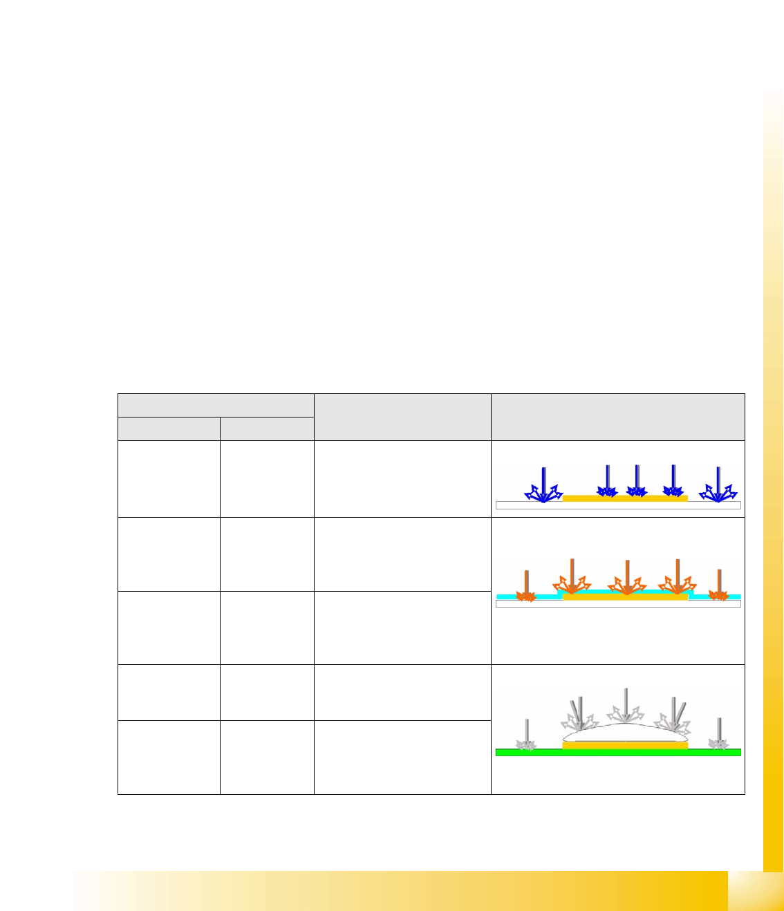
Illumination type/color PCB material Example
SST24 SST34
Blue Blue For recognition of gold or silver
colored fiducials on white
(ceramic) material
e.g. gold on ceramic
Infrared (IR)
diffuse
Red, diffuse For recognition of fiducials
under soldering paste and of
matt coated fiducials, plus
fiducials on glass sheets.
IR penetrates soldering paste and illuminates
covered structures.
IR steep is
always
combined with
diffuse
Red steep is
always
combined with
diffuse
For recognition of shiny coated
fiducials
White, diffuse Red, diffuse For recognition of matt
fiducials on any PCB material
and PCB surface.
Fiducials tin-plated with hot air
White steep is
always
combined with
diffuse
Red steep is
always
combined with
diffuse
For recognition of fiducials with
shiny surfaces
SIPLACE Vision - Teaching Fiducials
Fiducial shapes Synthetic Fiducials for Position Recognition Applications
Student Guide SIPLACE Vision (Customer)
SIPLACE Vision - Teaching Fiducials Edition 12/2008 EN
138
6.2.1.5 Algorithm Setting
In contrast to the algorithm settings for ICOS, measuring methods can not be selected or deselected
here.
In the SIPLACE Vision method, you can only change parameters or quality thresholds.
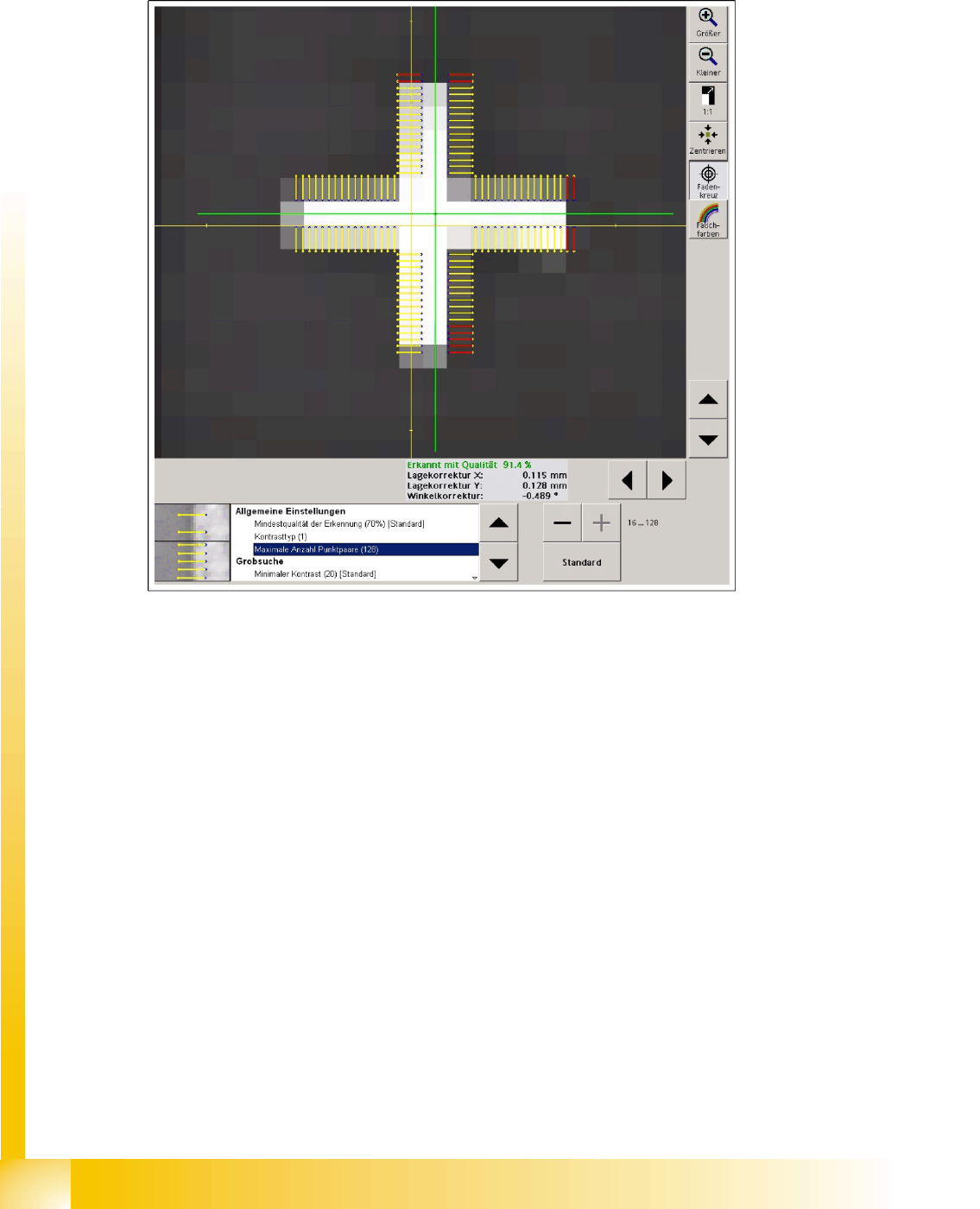
6-7: Algorithm setting shown with cross fiducial as example
The Minimum recognition quality of 70% is set so that no fiducial shape faults will lead to incorrect
calculation of the fiducial reference position and therefore to a placement offset.
Contrast type ’1’ indicates a light fiducial on a dark background. If you evaluated a dark fiducial on a
light background, contrast type ’-1’ would be shown.
The minimum number of image pairs can be increased or reduced in steps of 8. The default value
is 64. The cross-shaped fiducial has 8 image pairs for the edge on one side of the cross. If similar
structures are expected near the fiducial area, in the camera field of vision, the number of image pairs
should be increased accordingly to ensure reliable recognition of the shape.
SIPLACE Vision - Teaching Fiducials
Synthetic Fiducials for Position Recognition Applications Fiducial shapes
Student Guide SIPLACE Vision (Customer)
Edition 12/2008 EN SIPLACE Vision - Teaching Fiducials
139
With Subsampling the system combines a number of point pairs to one evaluation point or a so-called
moxel. The number indicates how many points are summarized on each page to facilitate faster
calculation. The fine structure (extremely thin bar widths) setsthis parameter to its standard value.
The Distance between points is set to the respective default value through the tolerance setting for the
fine structures.
This changes the distance between the points for the light foreground and dark background.
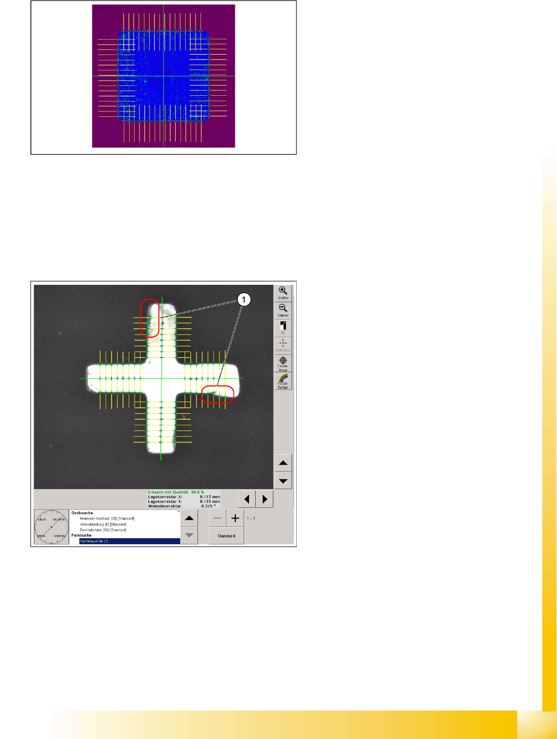
6-8: Minimum difference in contrast
Minimum contrast is set to ’20’ as a default,
meaning that a contrast difference between purple
and blue in the pseudo colors image is enough for
that structure to be recognized as a possible
fiducial contour. (concealed fiducial (blue) 39-55 /
background purple 15-20)
6-9: Fine search step for cross fiducial
Edge quality
The edge quality value for many interfering
structures can be set from 2 (default value) to 1.
this means that the edge is determined more
precisely. This also means that interfering
structures on the edge influence the measuring
result, since the permitted tolerance is very low.
If interference can be detected on the fiducial edge
(1), this parameter can be set to a value of 5. This
robust measurement method determines the edge
positions for the fine search with a greater
permitted tolerance or without checking (value 5)
the tolerance value for the edge position. (This
should be shown by the parameter ’Robust’ –
"Inaccurate".)