SIPLACE Vision Customer_en.pdf - 第14页
Introduction Camera Overview Individual Camera Types - Details S tudent Guide SIPLACE V ision (Customer) Introduction Edition 12/2008 EN 14 Overview of stationary cameras and other sensors 3.4.1 Individual Camera T ypes …

Introduction
Feeder Position Recognition Camera Overview
Student Guide SIPLACE Vision (Customer)
Edition 12/2008 EN Introduction
13
3.3.2 Feeder Position Recognition
SIPLACE Vision performs feeder position recognition directly before placement begins. The procedure
measures various feeder-specific system fiducials or geometric data for tape pockets, to determine the
actual component pickup position for the respective feeder track.
Before placement begins for a new job, the new X-series component tables are measured with the
PCB camera, by optically centering two fiducials per location.
The two table fiducials are also measured for these tables. These values are used to calculate the
pickup position of each feeder.
When using components which are smaller than 1.0x0.5 mm (0402), the system measures the
empty tape pockets for the respective track, directly before the pickup position.
3.4 Camera Overview
Overview of component cameras in placement head
Parameters C&P20
Camera
C&P12
Camera
Standard
C&P12
camera
0603 mm
(0201) ‚HR’
C&P12
camera
0402 mm
(01005)
C&P6
Camera
For placement head C&P20 DLM2 12 DLM2 12 HR DLM2 12
01005 option
(D series)
DLM2
C&P6
SST 23 28 29 38 29
Resolution [µm] 17 50 26 18 26
Field of [mm²] 8 x 8 24.5 x 24.5 24.5 x 24.5 20 x 20 32 x 32
Min. CO size [mm²] 0.2 x 0.2 0.5 x 0.5 0.3 x 0.3 0.2 x 0.2 0.5 x 0.5
Suitable for min. CHIP size 01005 0402 0201 01005 0402
Max. CO size [mm²] 6 x 6 18.7 x 18.7 18.7 x 18.7 16 x 16 27 x 27
Min. lead pitch [µm] 300 400 300 100 300
Min lead width [µm] 100 200 150 100 150
Min. ball pitch [µm] 400 450 250 250 300 (350 if
component >
18 mm)
Min. ball [µm] 200 250 140 140 150 (200 if
component >
18 mm)
Illumination levels
(programmable)
5
(5)
4
(5)
4
(5)
4
(5)
4
(6)
Teaching /centering the
component presentation
angle
In 0° / 90°
steps
/ placement
angle
In 0° / 90°
steps
/ pickup angle
In 0° / 90°
steps
/ pickup angle
In 0° / 90°
steps
/ pickup angle
In 0° / 90°
steps
/ pickup angle
Introduction
Camera Overview Individual Camera Types - Details
Student Guide SIPLACE Vision (Customer)
Introduction Edition 12/2008 EN
14
Overview of stationary cameras and other sensors
3.4.1 Individual Camera Types - Details
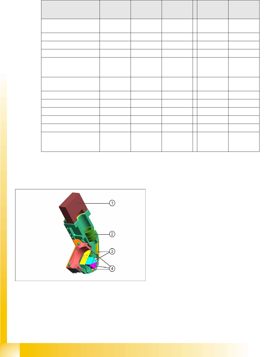
3.4.1.1 CO Camera C&P20 SST 23
Parameters IC
camera
IC
camera
FC
camera
KOPLAN
ILD2200 (spot
laser)
3 D KOPLAN
IVP (line laser
ONLY X2/X3)
For placement head TWIN with IC
camera
D1 TWIN with
IC camera
TWIN with FC
camera
TWIN TWIN
SST 33 36 25 17 37
Resolution [µm] 41 80 16
Field of vision [mm²] 65 x 50 39 x 39 19 x 19
Min. CO size [mm²]
CHIP component with
designation
0.5 x 0.5
0402
0.8 x 0.8
0603
0.2 x 0.2
01005
Max. component size
[mm²] single measurement
55 x 45 32 x 32 16 x 16 50 x 50
Min. lead pitch [µm] 300 400 250 400 500
Min. lead width [µm] 150 240 100
Min. ball pitch [µm] 450 560 140 ---
Min. ball [µm] 250 320 80 --- 400
Illumination levels 6 6 6 --- ---
Teaching /centering the
component presentation
angle
90° steps /
placement
angle
90° steps /
placement
angle
90° steps /
placement
angle
Description
position
Description
position r. 90°
step
Legend
1. Camera sensor
2. Lens system
3. Mirror system
4. Five programmable illumination levels
Introduction
Individual Camera Types - Details Camera Overview
Student Guide SIPLACE Vision (Customer)
Edition 12/2008 EN Introduction
15
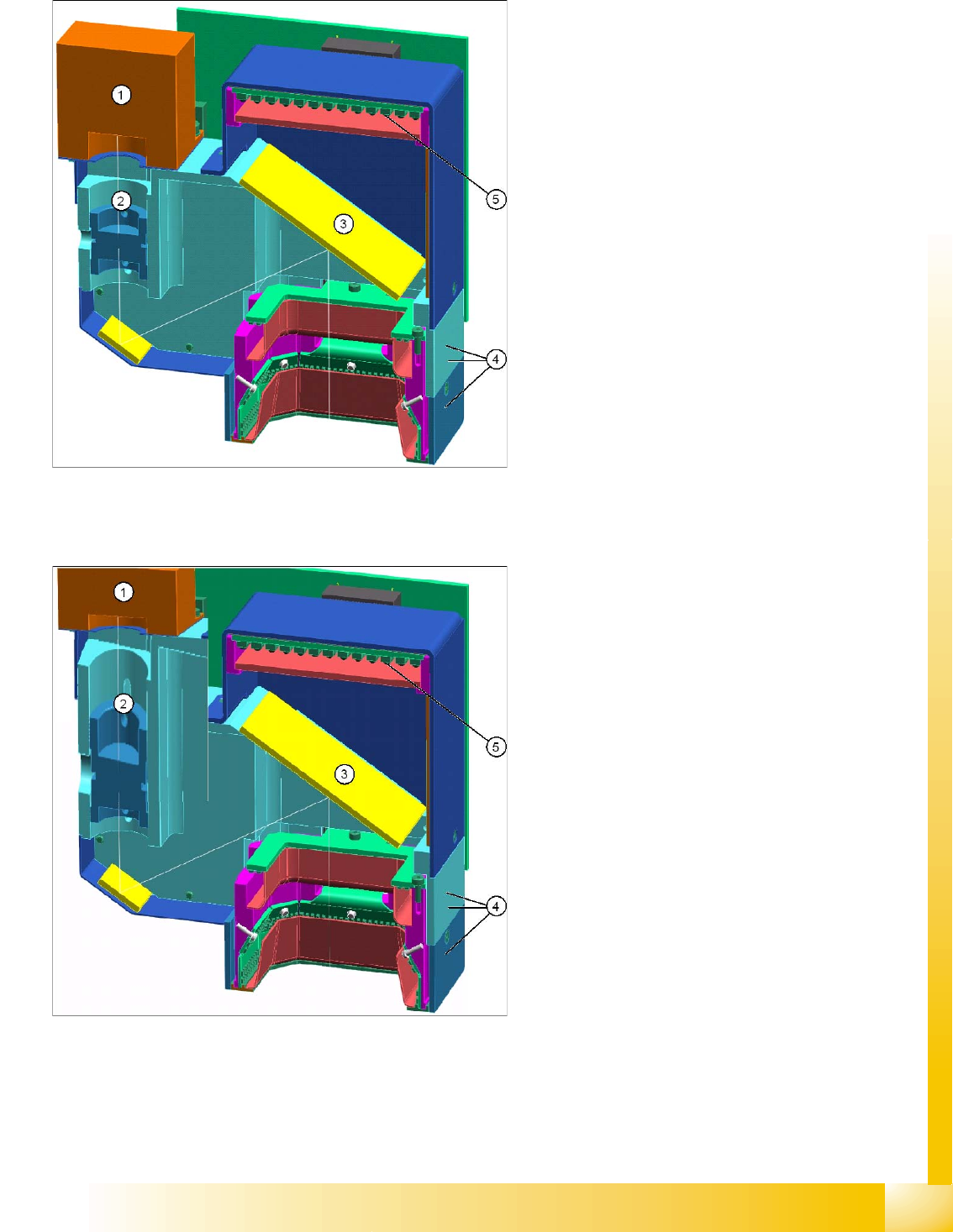
3.4.1.2 CO Camera C&P12 SST 28
3.4.1.3 CO Camera C&P6 (C&P12 'HR') SST 29
Legend
1. Camera sensor
2. Lens system
3. 45° mirror system
4. Three programmable illumination levels
5. 0° illumination level programmable
Legend
1. Camera sensor
2. Lens system
3. 45° mirror system
4. Three programmable illumination levels
5. 0° illumination level programmable