SIPLACE Vision Customer_en.pdf - 第154页
SIPLACE Vision - Teaching Fiducials Feeder Position Recognition Fiducials Component Pocket Fiducials S tudent Guide SIPLACE V ision (Customer) SIPLACE Vision - T eaching Fiducials Edition 12/2008 EN 154
SIPLACE Vision - Teaching Fiducials
Component Pocket Fiducials Feeder Position Recognition Fiducials
Student Guide SIPLACE Vision (Customer)
Edition 12/2008 EN SIPLACE Vision - Teaching Fiducials
153
Teaching pickup position fiducials (in extreme exceptions only)
Teaching - prerequisites and menus:
X Creates a fiducial in SIPLACE Pro and defines this as a component pocket.
X Assign the fiducial to the feeder track of the required component (observe component sizes as
explained).
X The
Line Engineer level
is active.
X The machine (placement run) has been stopped.
X Open the
Set up
menu (the feeder position recognition fiducials are NOT part of the placement
information!).
X The menu buttons:
Component pocket list
and
Test component
are only active when the machine
has been stopped.
X Select the incomplete or required fiducial.
X The gantry will position over the standard pickup position.
X Illuminate (type and/or intensity) and teach (X/Y geometry) the pickup position fiducial for the black
blister tape accordingly.
X Test the pickup position fiducial with and without components in the tape.
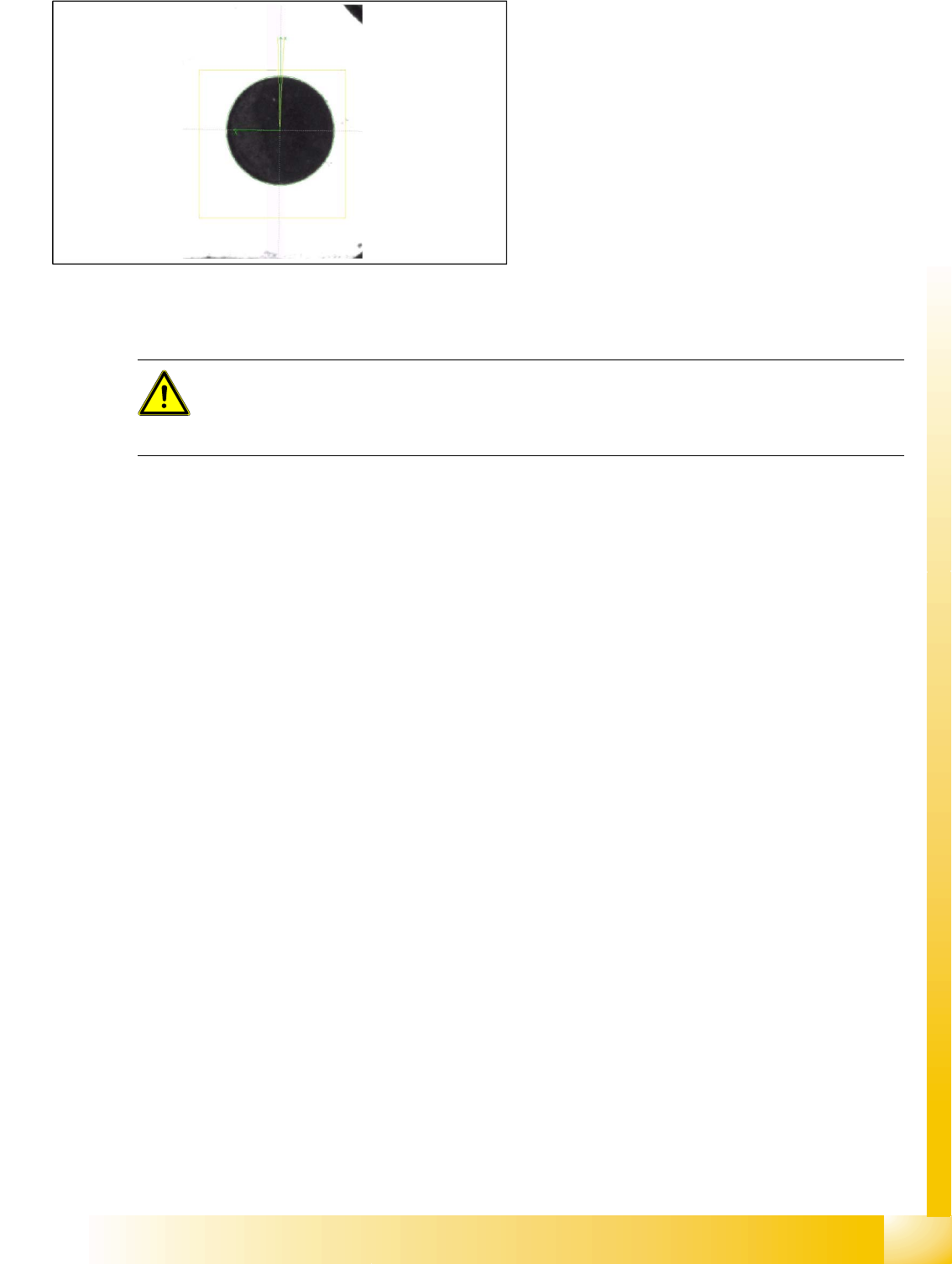
Feeder fiducial recognition
When components with a width of 08 mm or
wider are in the 0201(01005) 3x8mm S feeder
or when components which are narrower than
0.8 mm are in the 3x8 mm or 2x8 mm
standard S feeder.
The pickup position fiducial is automatically
generated from the CS body data.
The feeder fiducial from the pickup position is
derived from the construction offset. This is a
1.0 mm black machine circle fiducial.
ATTENTION:
This teaching is ONLY REQUIRED if the component sizes match the values specified above
and if these components need to be picked up from the black blister tape! (As of 2008, only one
such case is known.)

SIPLACE Vision - Teaching Fiducials
Feeder Position Recognition Fiducials Component Pocket Fiducials
Student Guide SIPLACE Vision (Customer)
SIPLACE Vision - Teaching Fiducials Edition 12/2008 EN
154

SIPLACE Pro 3.0 Programming Interface for Component Shapes
Step-by Step: Component Shape Import Component Shape Import and Data Conversion for SIPLACE Vision
Student Guide SIPLACE Vision (Customer)
Edition 12/2008 EN SIPLACE Pro 3.0 Programming Interface for Component Shapes
155
7 SIPLACE Pro 3.0 Programming Interface for
Component Shapes
7.1 Component Shape Import and Data Conversion for SIPLACE
Vision
7.1.1 Step-by Step: Component Shape Import
There are two ways to import component shapes:
1. LC import from line computer (UNIX or LINUX data systems)
or
1. XML import from another SIPLACE Pro system.
Make sure you complete the following CS import steps in the correct order:
CS Import: In both methods, make sure that all errors displayed for the current import (LCU import
or XML import) are solved. Please note that the import procedure also includes the SST files for the
entire database.
No. of CSs: LCU import is only suitable for individual component shapes. Data from SIPLACE Pro
2.0 will be converted to version 3.0.
Type & inspection conversion: This step converts the body shape and component type for
SIPLACE Vision.
Make sure you solve any type/inspection conversion errors displayed at this stage.
Integrity check: This step checks the parameters and their relationship to the converted
components types (check component shape).
Make sure you solve any integrity check errors displayed at this stage.
Camera and nozzle conversion: This step selects and allocates the new digital camera types and
nozzles for the C&P20 heads.
Make sure you solve any camera/nozzle conversion errors displayed at this stage.
X feeder allocation: This step selects and allocates the new feeder types. These are needed during
the placement process with C&P20 heads.
Make sure you solve any X feeder allocation errors displayed at this stage.
Report tools: This function gives you an overview of the component shape state for the newer
SIPLACE Vision system and the older SIPLACE ICOS system.
The Report Tool contains a graphical representation of the component shape, with details of
dimensions, offsets, pins, balls and their orientation, as well as a tabular overview of the body shape,
component type, lead type, body and overall dimensions, plus a Requires separate group
description.
It provides a diagram of the relationship between component shape and component and shows you
where the component shape is used.
Critical components: To maintain the correct data for special component shapes, the original
datasheets are used for these critical components.
The body color can be altered to improve the clarity of the image (e.g. red coloring).
Difference descriptions: The final step provides a description of differences in the component
shape data. This is only compiled for Nonstandard, DPACK, Connector and Socket shapes.
The body color can be altered to improve the clarity of the image (e.g. blue coloring).
NOTE: Observe the offset values!
Changing the lead group offsets directly influences the placement accuracy or component
placement.