SIPLACE Vision Customer_en.pdf - 第159页
SIPLACE Pro 3.0 Programming Interface for C omponent Shapes Adopting the Standard Component Shape from the SIPLACE Pro Instal lation in the Customer's Component Shape Database Converting t he S tudent Guide SIPLACE …
SIPLACE Pro 3.0 Programming Interface for Component Shapes
Converting the Component Shape with LC Import from a UNIX/LINUX Line Computer Converting the Component Shape Type
Student Guide SIPLACE Vision (Customer)
SIPLACE Pro 3.0 Programming Interface for Component Shapes Edition 12/2008 EN
158
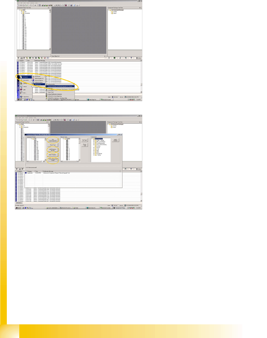
7.2.1 Converting the Component Shape Type
SIPLACE Vision (or SV) requires you to define a body shape, component type and lead type.
Program Start
Programming desk
The first conversion refers to the component
type and the CS inspection mode.
This is followed by Check Component Shape,
which involves checking the lead type and the
allocation of the component type.
The new - digital - camera types can be added
in the Add Cameras/Nozzles menu.
If the new X machines are to be used with X
feeder tables (required for C&P20 heads),
enable the Add X Feeders menu.
After each of these steps (LC import/conversion
type/Inspection) check the report lists for any
errors or warnings. Changes to the individual
component shapes in the CS database should be
documented in a suitable report or printout.
SIPLACE Pro 3.0 Programming Interface for Component Shapes
Adopting the Standard Component Shape from the SIPLACE Pro Installation in the Customer's Component Shape Database Converting the
Student Guide SIPLACE Vision (Customer)
Edition 12/2008 EN SIPLACE Pro 3.0 Programming Interface for Component Shapes
159
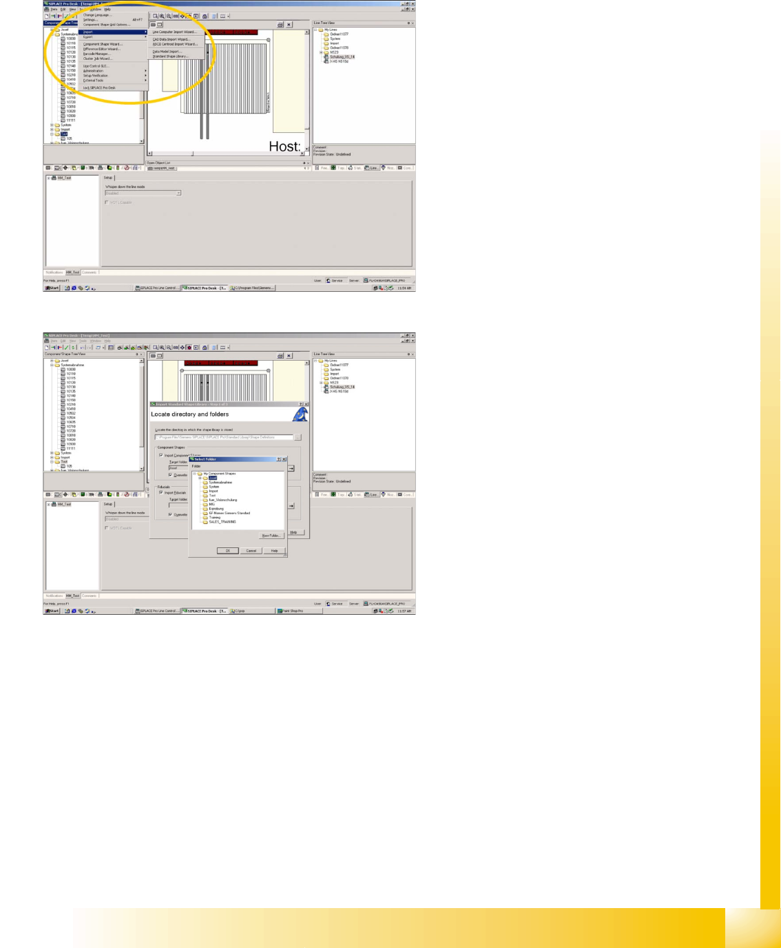
7.2.2 Adopting the Standard Component Shape from the SIPLACE Pro Installation in
the Customer's Component Shape Database
The installation of SIPLACE Pro software also installs a revised version of the Standard Siemens CS
Database. These component shapes can then be imported into the customer's CS database.
Program Start
Pull down menu
->Tools
-> Import
-> Standard Shape Library
This opens the first window of three steps, for
adoption of new standard CS descriptions.
Selecting the standard CS source directory
and target directory
Set source directory in the
… Browser menu
->at C:\Program files\Siemens Siplace\Siplace
Pro\Standard Library\ Shape Definitions
.
Set target directory in the
… Browser menu
-> at component shape subdirectory .
SIPLACE Pro 3.0 Programming Interface for Component Shapes
Converting the Component Shape with LC Import from a UNIX/LINUX Line Computer Adopting the Standard Component Shape from the
Student Guide SIPLACE Vision (Customer)
SIPLACE Pro 3.0 Programming Interface for Component Shapes Edition 12/2008 EN
160
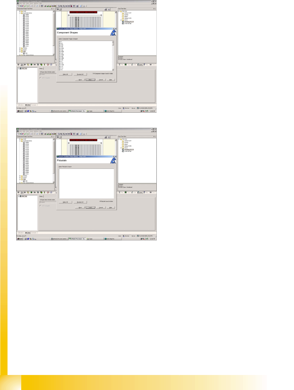
Selecting the standard component shapes to
be imported
Selection menu
-> for CS.
Fiducials will not be imported!
Completing the import
After importing the standard component shape,
you need to add nozzles and camera for the X
machine. This sequence of programming events is
designed to allow you to still compile data without
X machines.