SIPLACE Vision Customer_en.pdf - 第165页
SIPLACE Pro 3.0 Programming Interface for C omponent Shapes Programming Interface for SIPLACE Vision Parameterizati on Programming the Component Shapes in SIPLACE Vision S tudent Guide SIPLACE Vision (Customer) Edition 1…
SIPLACE Pro 3.0 Programming Interface for Component Shapes
Programming the Component Shapes in SIPLACE Vision Programming Interface for ICOS Parameterization
Student Guide SIPLACE Vision (Customer)
SIPLACE Pro 3.0 Programming Interface for Component Shapes Edition 12/2008 EN
164
7.3.2 Programming Interface for ICOS Parameterization
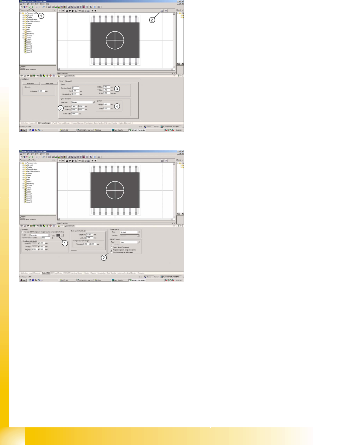
Legend
1. Integrity test for component shape in the
editor.
2. Printout of the window contents.
3. Lead group offsets – defines the placement
center of the component.
4. Contact length and width of Gullwing lead.
5. Geometry only for Gullwing/J-Lead/
Wraparound/ Balls (when ICOS and SIPLACE
vision can be edited with the same CS
programming).
Legend
1. The body color can be individually defined for
more clarity e.g. orange for Requires separate
group description.
2. The Vision systems require separate
descriptions for the different lead groups
(Requires separate group description).
In addition detect flipped component (detection of
flipped components) stop immediately on pickup
error (empty track after a previously defined
amount of component pick-up trials) Orientation
(only for component shapes with asymmetric
connectors) Description incomplete and so on can
be selected for these component shapes, when
using SIPLACE Vision at the stations.
The function "Deactivate Check for minimal
Comp.shape structure" allows you to place small
quantities of components which are smaller than
those permitted for the camera specification.
ONLY select this function if absolutely necessary
as the placement accuracy may be less than that
specified on the machine data sheet..
SIPLACE Pro 3.0 Programming Interface for Component Shapes
Programming Interface for SIPLACE Vision Parameterization Programming the Component Shapes in SIPLACE Vision
Student Guide SIPLACE Vision (Customer)
Edition 12/2008 EN SIPLACE Pro 3.0 Programming Interface for Component Shapes
165
7.3.3 Programming Interface for SIPLACE Vision Parameterization
Select Requires separate group description to copy the programmed parameters from ICOS to SIPLACE
Vision.
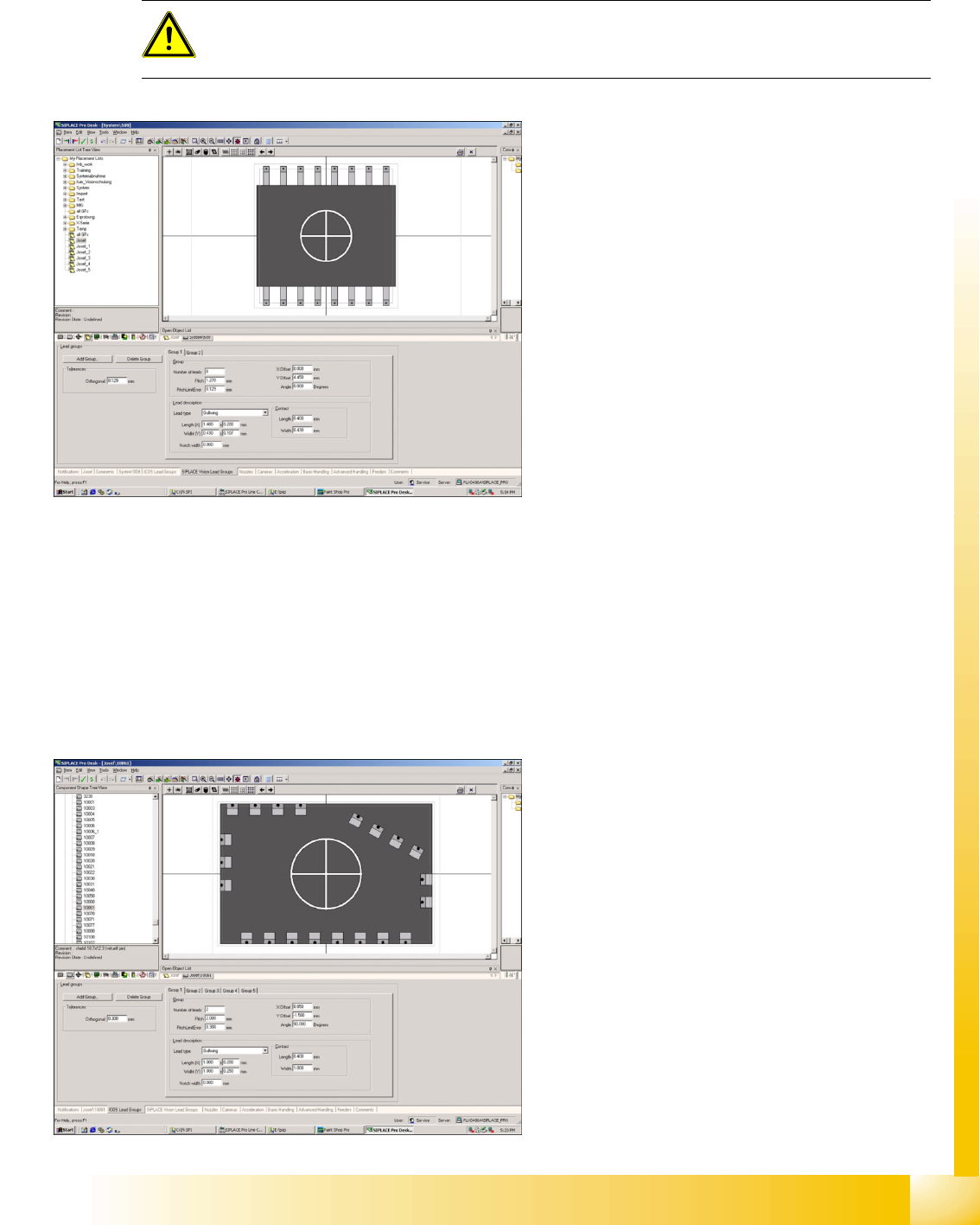
7.3.4 Application Example for 'Requires Separate Group Description'
This example uses the programming of a Shield to show the different programming procedures for the
two Vision systems.
ICOS uses a programming trick to make sure that the outer edge of the Shield is recognized: virtual leads
are defined along the outer edge, which the ICOS Vision system searches for with ROW (CORNER and
LEAD disabled) mode only. The lead ends and the position information for each shield side are
recognized during component centering.
ATTENTION:
Disable Requires separate group description to delete the SIPLACE Vision parameter set
WITHOUT BACKUP!!!
After enabling Requires separate group
description, you will be given the opportunity to
program different lead group descriptions for
SIPLACE Vision. A copy of the ICOS parameters
(see above) forms the basis for programming in
SIPLACE Vision.
Shield programming in ICOS.
SIPLACE Pro 3.0 Programming Interface for Component Shapes
Programming the Component Shapes in SIPLACE Vision Application Example for 'Requires Separate Group Description'
Student Guide SIPLACE Vision (Customer)
SIPLACE Pro 3.0 Programming Interface for Component Shapes Edition 12/2008 EN
166
For SIPLACE Vision, CORNER recognition is programmed on the outer edge of the Shield.
For SIPLACE Pro, there are two programming options:
Programming the corner positions as the basis for definition of the coordinates for the lead start and
end recognition vectors.
Programming the component center as the basis for the definition of the lead start and end
recognition vectors.
A further alternative is to directly correct/program the X/Y offset values of a recognition position in
SIPLACE Vision. We particularly recommend this option for corners which can not be programmed with
an opening angle of 90°.
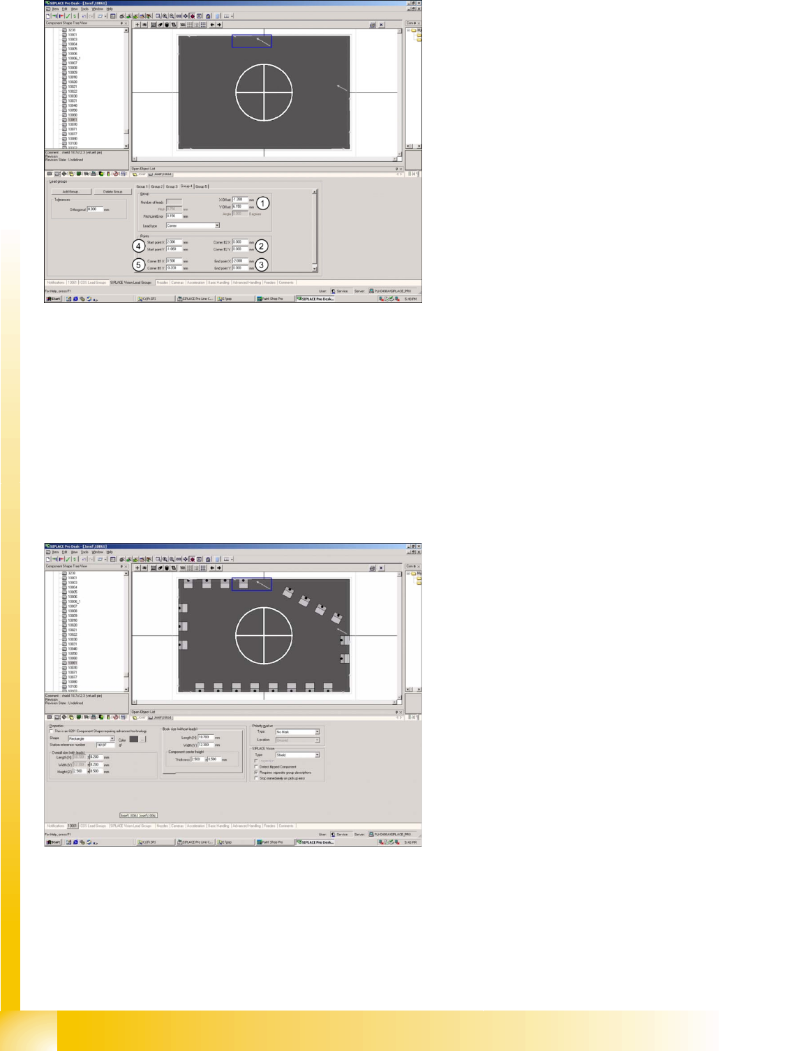
Legend
1. Corner offset from the component center.
2. Start point for the horizontal recognition
vector.
3. End point for the horizontal recognition vector.
4. Start point for 30° corner recognition vector.
5. End point for 30° corner recognition vector.
This programming window for body dimensions
shows ICOS lead group programming, with 21
leads in five groups.
The arrows in the Shield corners show the
programming of SIPLACE Vision recognition
vectors; the blue window marks one of five
programmed corners.
At the end of component shape programming, the
integrity check (see above) can be used to check
the dataset for completeness and correctness
(new in SIPLACE Pro 3.0).