SIPLACE Vision Customer_en.pdf - 第180页
Feature PIN type Shape & Meas. position 0 degree orientation Filter for feature (terminal) Speciality / comment used at ... Possible to use at ... Reason for reject of the GF- type Rectangle feature since 702(sv4.0.1…
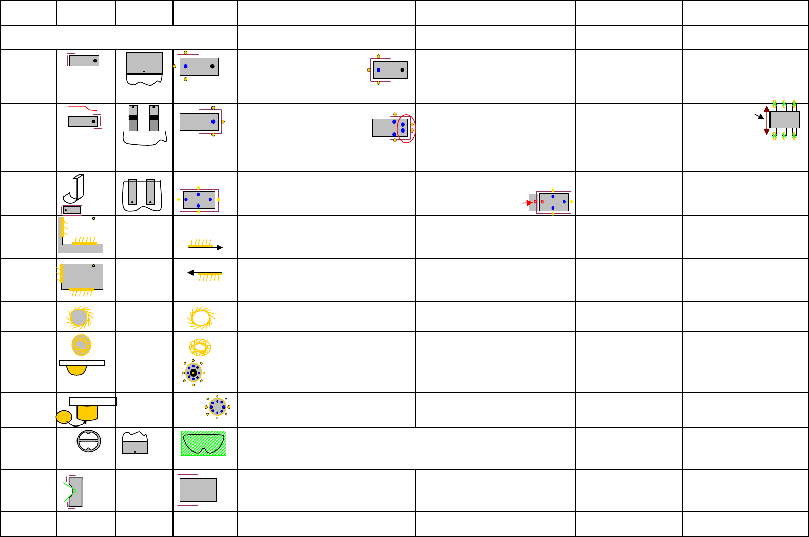
Feature
PIN type
Shape & Meas.
position
0 degree
orientation
Filter for feature
(terminal) Speciality / comment
used at ...
Possible to use at ...
Reason for reject of the GF-
type
only with (cubic) rectangle body
Bare Die
Pos./angle deviation / X/Y-body
dimension
WrapAround
Is the PIN-width tolerance of wide PINs
increased above
40% the pixel pair at the meassured
PIN-end is divided into 2 pairs.
Same happen on extreme wide PINs.
Wraparound could be dark on bright
background
CHIP; MELF; Moulded;
Dpack (wide PIN);
Socket;Connector;
Nonstandard;
Pos. / angle deviation /
Filter to large or small / PITCH /
PIN width / PIN pos. / PIN group
pos.
For MELF X-body length check
Gullwing
Is
the
PIN width
tolerance
of
wide
PINs
increased above 40%
the pixel pair at the meassured
PIN-end is divided into 2 pairs.
Same happen on extreme wide PINs. /since
702 (SV 4.0.1) the gullwings could be inspected
on 'Co-linearity of the PIN Ends in one group.
At small PIN dimensions the 3 (blue)
marks for the bright PINs covering each
other. The position of divided Pixelpairs
are more precise if a Notch is
programmed
ECV; SOT; SOxx; QFP;
Socket; Connector; Dpack
(small PINs and wide PIN);
Nonstandard
Pos. / angle deviation /
Filter to large or small / PITCH /
PIN width / PIN pos. /
PIN group pos.
J-Lead
Use only if the PIN is really a
J-Lead!
If only one Pixel pair is
missing the recognition fail!!
SO-J; PLCC; Socket;
Connector; Nonstandard
Pos. / angle deviation /
Filter to large or small / PITCH /
PIN width / PIN pos. / PIN group
pos.
Corner Out ----
recognition always the same length and with
same distance to the corner. (simplfy
calculation). Do not program the vectors too
long. Otherwise the angle determination is not
The bright shield is at the left side of the
recognition vector! Single feature - NO
row or grid programming
Shield; Nonstandard
corner position
Corner Inside ----
recognition always the same length and with
same distance to the corner. (simplfy
calculation). Do not program the vectors too
long. Otherwise the angle determination is not
The bright shield is at the left side of the
recognition vector! Single feature - NO
row or grid programming
Shield; Nonstandard
corner position
Polygon circle
dark (drillng) ----
Single feature - NO row or grid
programming
Shield; Connector;
Nonstandard
polygon position / polygon
diameter (because of filter dim.)
Polygon circle
hell ----
Single feature - NO row or grid
programming
Shield; Connector;
Nonstandard
polygon position / polygon
diameter (because of filter dim.)
Balls ----
the ring image occure only with a flat
illumination direction to hemisperical
structures.
BGA; Socket; Connector;
Nonstandard X/Y PITCH / Ball-position
Columns ----
the circle image occure only with a steep
illumination direction to flat round
structures.
CCGA; Socket;Connector;
Nonstandard X/Y PITCH / column-position
Blop
Socket; Connector;
Nonstandard Blop position / Blop area
PIN with notch
respective the
PIN type
The notch is NOT actively searched; Filter
avoid only the PIN center. Other
possibilities higher width tol.
only at Nonstandard and
Connector (not to edit)
respective to the kind of Pin
(Gullwing/Wraparound) is the
filter divided. The measurem.
criterias are unchanged.
Centering pin
not centered in
vision system
Centering Pin height could be programmed only
in SiPLACE Pro .
feature to increase the overall component
height since SC/MC603
only at Nonstandard and
Connector
in future (?) to move slowly for
the centerpin height
Depend strongly on fitting illumination.
Calculate a relation between programmed rectangle and real Blop area -
program the X/Y-dimension tolerance large enough.
Feature could be defined in algorithmn (filter type 91) for dark.
Body without any other feature
Edition 3.0 17.10.2008 GF kurzref_A4_DE.xls features Siemens Ind. Sec EA1 SC E

Feature
PIN type
Shape & Meas.
position
0 degree
orientation
Filter for feature
(terminal) Speciality / comment
used at ...
Possible to use at ...
Reason for reject of the GF-
type
Rectangle
feature since
702(sv4.0.1)
The rectangular feature could be a feature of
the comp. Beside the electr. Terminals. But it
could be also the hole component.
the min. respectively thie max. size
depend on the camera type. only for Nonstandard
Edition 3.0 17.10.2008 GF kurzref_A4_DE.xls features Siemens Ind. Sec EA1 SC E

Function: Menu 1 Menu 2 Menu 3 Menu 4
Nozzles
Cameras
acceleration
Vacuum at pickup:
Normal Vacuum; it is activated when the
nozzle touch the component.
Early Vacuum; it is activated when the Z-Axis
trigger the LB-topb (DLM). C&P20 head: The
Vacuum ispermanent on the nozzle. For
comp.'s smaller 6mm is recommended to
switch to early Vacuum by default.
pickup correction:
autom. pickup-pos-corr. ON? is only
deactivated for 'MELF' and ODDshape GF's.
A Z-pickup height corr. is always active!!
X/Y/Z pickup position (offset) program a
shift of the nozzle contact point to the GF-
center. the comp. is picked there to avoid
leaking or swiffle of an unsymetric c.
MTC-acceleration:
Y-axis valid for the feed axis of the Magazine
carriers
Z-axis valid for the lift axis of the respective
Magazine tower
centering:
activate centering: is deactivated in very rare
exceptions (placement force measurement).
Reduce optical width : is as a LC-Import /re-
export function implemented.
coplanarity: is to activate here. The coplan.
Tolerance is the solder paste thickness at the
PCB-editor.
Dipp: Special mode for Flux material at comp.
terminals in DIP-modul on feeder area.
It isto select: Dipp
/ Dipp before Vision/Vision
before Dipp
force for Dipp / Waiting time in Flux
Pickup pos. offset to the standard pickup
pos. in center of the feeder pickup window
Feeder fiducial: (for X-feeder)
A programming option forteached feeder
position recognition fiducial. This is an option
for special cases or if the general function fail.
Transport speed: (for X-feeder)
The transport speed for the comp. tape could
be reduced to middle or slow.
component pitch: (for X-feeder transfered
into feeder)
The comp. pitch in the reel -information for
traceability at S-feeder.
Comments
Airkiss at
placement/re
turn
adjustable
airkiss
C&P20/TWIN.
At DLM head -
time
controlled in
placement
sequence.
Speed profile for pickup:
Profile downward: 1 - pickup stand. - with contact (2N) / 17 - Pickup contactless (with autom. height teaching at 1st pickup) 21 pickup with minimal force (1N Twin only) 22 ----
Profile upward: 2 pickup stand. Normal accel. upward 3 start slowly upward (20ms for full vacuum) 4 - start very slow upw. (very time consuming) 23 ---
Speed profile for placement: downward define the placement force for the component.
Profile downward: 5 placement stand. 2N -force 7 - increase -force 3- 5(C&P) -10N IC/TWIN 8 - increased -force with slow touch down (+20ms) 3- 5(C&P) -10N IC/TWIN
25 very high -kraft 11-15N TWIN 26 very high force w. slow touch down 11-15(30) TWIN 27 very low -force 1.0N only TWIN 28 very low -force w. slow touch down TWIN 29/30 --- 31
smooth placement (for 0201)
Profile upward: 9 standard upward 10 slow start upward (+~20ms) 24 ---?
sorted according head type / selected that they fit for the body dimension and comp. height / they should have enough holding force to the comp. surface during the placement sequence
(nozzle material) see nozzle overview
placement head specific; consider maximum comp. size; consider min. pitch and structures; see camera overview
The acceleration of axes base on the SIPLACE machine type with the fastest axis of the selected type. Therefore program this reduced values only with assistance of ONLINW HELP
information. The values are programed in absolute values in 'g' or r/sec².
-> for shiffted components on nozzle: 1. check selected nozzle, nozzle material 2. check acceleration X/Y respect. / and Star axis
-> for turned comp.'s (angle error in the camera) 1. check selected nozzle, nozzle material 2. check accel. Z-axis upw. 3. reduce accel. DP-axis.
-> comp.-pickup error 1. check feeder 2. check special mode for improvement 3. reduce (additional) accel. Z-axis upward.
Feeder
Comp.-presence check: activ./deactiv. for Pickup and/or placement (deselect both or select NO Vacuum)
-> Normal: at C&P6/12 head - a vacuum check is done / C&P20 - comp. presence check with comp.-sensor / TWIN - vacuum check
->
Extended: at C/P12 /20 head - comp. presence check with comp. sensor (option) C&P6 /TWIN ---
-> comp. thickness: DLM12 with comp.sensor opt. measure comp-thickness & at the same time vacuum check / C&P20 measure
comp.thickness at nozzle / TWIN ---
-> comp. thickness and NO Vacuum: C&P12 with comp. sensor opt. & C&P 20 head measure comp. thinkness ./ TWIN ---
For X- Feeder programming of GF / component please note:
-> with manual programming of the Feeder the programmed pickup offset of the org. feeder are NOT taken and prog.
-> with automatic programming of the Feeder the programmed pickup offset of the org. feeder are taken and prog.
A meaningfull comment for the component shape help the operator and programmer.
basic
handling
Placement force:
values for C&P head from 1N to 5N
for IC head (Fx ma.) 1-10N
for TWIN head standard 1-15N / Highforce 1-30N
Please Note: You have to select for this Function additionally the right profil in menu
'Extended handling'; otherwise the placement head continue work with 2N placement
force.
extended
handling
Edition 3.0 17.10.2008 GF kurzref_A4_DE.xls Handling data Siemens Ind. Sec EA1 SC E