SIPLACE Vision Customer_en.pdf - 第195页
linienfarbe 192,26 ,128 Pin description Wraparound: - could be dark / Gullwing: have a c ontact length short er than the pin length / J-Lead have a 4- sided filter / ICOS Ball filter could NOT distinguish balls from circ…
linienfarbe 192,26,128
Pin description
Wraparound: - could not be dark / Gullwing: have a contact length shorter than the pin length /
J-Lead have a 4- sided filter / ICOS Ball filter could NOT distinguish balls from circles /
corner and polygon circles for Shield recognition aswell as Blops and Columns are ONLY for
SIPLACE Vision to program.
Pin's are searched in width and length At Gullwings the recognition area is defined by the
shorter contact length.
Width tolerance
Set the filter but ICOS do not measure the width.
Full marking line for PIN group show that
Drag&Drop function is activated at setting.
Tolerances - ortogonality
Important only for ICOS systeme! 4 sided comp. shapes should be programmed here
with an ortogonality threshold of approx. 10-20% (ident. with pitch tol.) of the pitch.
The opposite groups may differ with their center positions from the center coordinate
line. This is a reject criteria if the programmed limits are exceeded.
Coordinate cross show the comp.
reference of the programming
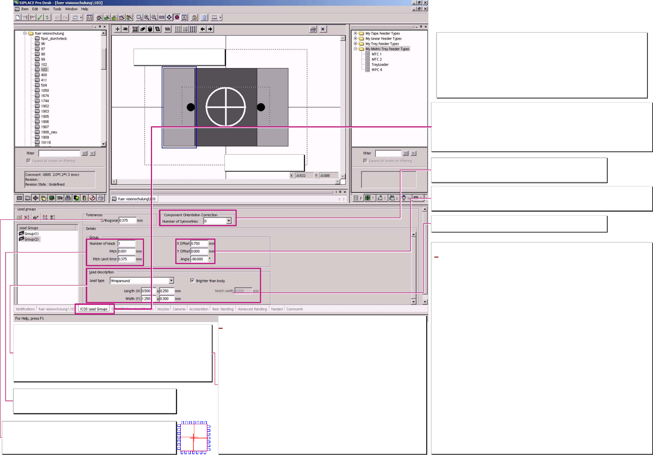
Component orientation correction
ONLY for SIPLACE Vision starting with Station-SW 603 on the machine.
Valid ONLY for Components with asymmetrical terminal features!!
Otherwise you create accidential placement angle errors!! ;-C !!
Notch / ❑ brighter than body
Only for Nonstandards which are scheduled to SIPLACE Vision.
*Gullwing (gull wing)
pin's are measured on the Pin end.
The shorter the contact length of the pin is programmed the more precise the centering get the Pin
bending.
Wraparound (‚wrapped around the body edge’)
pin's are measured at the counter side of the pin end (you might call it the pin beginning’) mean at the
edge where it is wrapped around the body edge.
The pin could be programmed that it is outside orientated this avoid measurement at pin ends with
notches (This pin’s with notches could ICOS not recognize).
ONLY SIPLACE Vision could recognize the pin's which might be dark on a bright background.
e.g. for flat illumination on components with white ceramic body there, the pin metal reflect not back
to the camera.
J-Lead
pin's are measured on all 4 sides of the lead.
The illumination of the pin bottom rounding come from all 4 illumination levels of the cameras.
Ball (hemispherical terminal)
pin's are recognized at the terminal center.
With flat illumination direction the top of the terminal is not visible. This creates the so characteristic
ring shape for the Ball position in camera image.
Correct and damaged Ball’s could not be distinguished with ICOS camera technique.
Group (parameter)
In the editor is the Pitch shown a fault if the pitch is smaller than the Pin width.
The Pitch tolerance should not exceed 10-20% of the pitch. This may lead to
overlapping measurement windows for the pin recognition.
Lead group coordinates
This coordinates have to align CHIP and MELF pin edges to the body edges.
The position of the lead groups for integrated circuits could be programmed that way that the drawing has
no connection to the body or that the pin group looks to be inside the body dimension.
Programming window titel (according function)
‚pin's for both Vision systems’
– with SIPLACE Vision function extention:
‚ICOS pin groups only’–
Think at EACH programming of a component shape on the possibility of a wrong pick up of the
component.
If such sideway picked (billboard effect) or upright picked (tombstone effect) components are
NOT recognized by the camera they are placed and cause the functional defect of the board.
An extreme example is the SOD323;
Is this is programmed for ICOS-Visionsystem as a comp. with 2 Gullwings so it might happen
caused by nozzle and/or feeder difficulties that the DPM rate increase up to 1000 or 20000.
A programming for ICOS as a CHIP component (Comp. as wide as pin's & Wraparound pins
inside instead of Gullwings outside) recognize the wrongly picked component safely
(at SIPLACE Vision recognize each measurement algorithm this in Inspection).
Component shape
Pin - /Group data
* at this descriptions for training we assume that this component
shapes are also valid for machines with ICOS-systems.
Therefore, program here only Leads ICOS SW & ICOS Cameras could
recognize.
The programming desk is designed for users they do not use this on
the previous ICOS vision system
– for pure placement on SIPLACE Vision Machines (X/D) –.
Therefore, all the pin types are offered in this general programming
window. We describe trhis new pins for training in the SIPLACE Vision
programming window
If following Pin types are programmed here so ICOS systems could get
the data too and center those components optically.
Columns: In ICOS, they are identically illuminated to balls and
optically centered.
Blobs: They are programmed like J-leads (contact length/-width
equal to Pin length/-width). Therefore, they are illuminated like
J-Leads and optically centered.
Pin’s with prog. notches: according their optical impression they are
recognized in ICOS (or not).
Since SIPLACE Pro 5.2 you could sent also
Centering pins to ICOS systems. At no actual system an optical
recognition is done.
A programing overview about process reliability Editon for SIPLACE Pro 5.0 extended for 5.2
linienfarbe 192,26,128
Pin description
Wraparound: - could be dark / Gullwing: have a contact length shorter than the pin length /
J-Lead have a 4- sided filter / ICOS Ball filter could NOT distinguish balls from circles /
corner and polygon circles for Shield recognition aswell as Blops and Columns are ONLY for
SIPLACE Vision to program.
pin's are searched in width and length At Gullwings the recognition area is defined by the
shorter contact length.
Width tolerance
larger approx. 40% change the filter parameter for pin recognition respectively, a length width
relationship of less than 1:2 show the same changing on the filter.
Dotted marking line for PIN group shows that
Drag&Drop function is De-activated at setting.
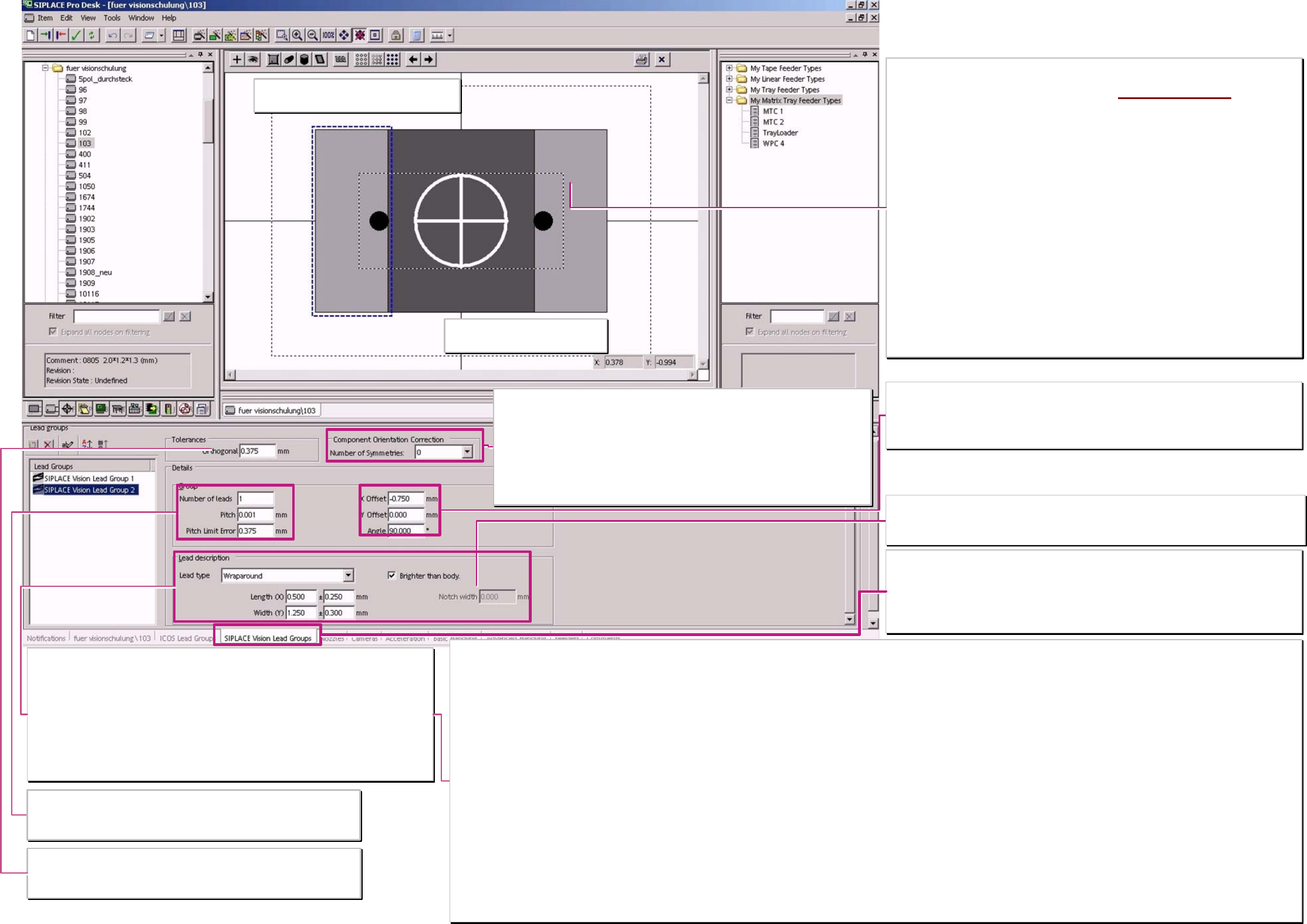
Tolerances - Ortogonality
ONLY important for ICOS systems!
In the inspection step algorythm of SIPLACE Vision the plausibility of the group
positions is automatically checked.
Coordinate cross show the comp.
reference of the programming
Component orientation correction
with unsymmetrical terminals they could be found with multiple measurements in different
angles. The TWIN turn the comp. in the different angles when the measurement before
failed. At C&P heads are the electronic images of th programming are turned. (anyway
time consuming).
For components with symmetric terminal features create a number more than 0 or 1 a
polarity placement error.
2 => 180° / 4 => 90° / 6 => 60° / 8 =>45° are the possible placement angles in which the
camera may recognize the asymmetric terminals.
Notch / ❑ brighter than body
Only for Nonstandard compomponents with Wraparound pins.
This programming of a notch avoid at the pin width center to set a recognition pixel pair for Pin
recognition.
Terminal types with a better programming and recognition in SIPLACE Vision than in ICOS!
Blop
Pin is measured in the center.
At ICOS are the straight edges programmed for short Gullwings.
The Blop learn and recognize the irregular connecting area. A comparison of size and center position guarantee that no structures are mixed up and therefore placement errors occur.
Columns
Terminal is measured in the center.
Such a circular area was programmed in ICOS also as a ball. SIPLACE Vision could distinguish with special filters balls from defects or columns. These Columns do not have the characteristic black
center position.
Polygon circles
Feature is measured in the center.
At ICOS balls are programmed & with teaching the illumination, contrast and the measuring method are set for the dark circle. drillings at Shields are often not specified and deviates widely.
In SIPLACE Vision each polygon circle has to be programmed for a single feature.
The measurement algorithm search along the tangential search lines for the brightness transition.
Corner (inside - / outside corners)
Feature is recognized on the outermost edges of the measurement vectors.
At ICOS are ‚virtual, short and wide Gullwing pins are programmed.
Short measurement vectors close to the edge recognize the edging dark bright transitions.
Minimum 3 corners have to be programmed for position determination of the component. Not 90° (45°- 135°) corners are the best programmed with the camera.
Wraparounds with notches Dark wraparounds on bright background
These pin's than not measured at the Pin width center the pixel pairs and measurement windows are positioned at the corners of the pin's. The pin side edge is measured with a pixel pair and the pin end
edge is measured with 2 pixel pairs. The notch width is NOT measured. The measurement algorithm for dark wraparounds on bright background are also only in SIPLACE Vision available!
Centering pins
This feature is NOT optically measured it is used to program the ’dynamic profile move slowly in to target height position’.
Group (parameter)
In the editor is the Pitch shown for faulty if it is smaller than the Pin width.
The Pitch tolerance should not exceed 10-20% of the pitch. This may lead to
overlapping measurement windows for the pin recognition.
Lead group coordinates
This coordinates have to align CHIP and MELF pin edges to the body edges.
The position of the lead groups for integrated circuits could be programmed that way that the
drawing has no connection to the body or that the pin group looks to be inside the body
dimension.
Programming window titel (according function)
for SIPLACE Vision functional extension:
‚SIPLACE Vision lead groups’
Pin programming parameter copied from ‚for both Vision
systems - with SV-functions only ICOS PIN groups
’
Setting the tick at ‚Require separate group description’ copy
the programming data from ‚ICOS-window into SIPLACE
Vision – programming window!
Deleting this tick erase the SIPLACE Vision programming
data immediately! ;-(
Separate Pin group descriptions are required when:
> the optical feature is NOT available in ICOS (see below)
> with the better camera technique the comp. Features are
better illuminated and recognized.
> the programming because of algorithm difficulties in ICOS
not fit to the real geometry.
> the terminal Inspection with SIPLACE Vision is remarkable
faster than with ICOS. (for SIPLACE Vision we use the full
number of terminal programmings)
Component shape Pin - /
Group data SIPLACE Vision
A programing overview about process reliability Editon for SIPLACE Pro 5.0 extended for 5.2
linienfarbe 192,26,128
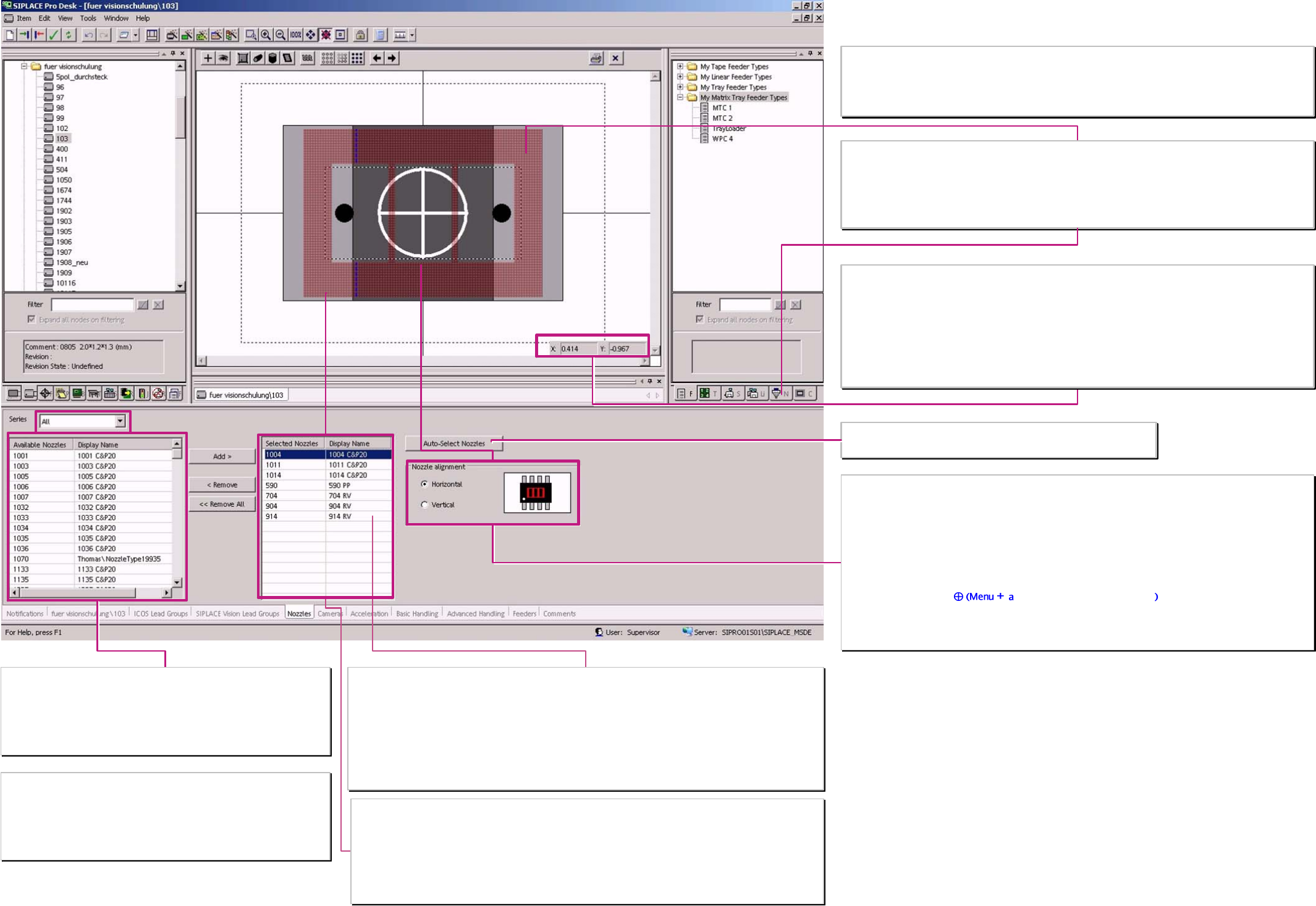
Nozzle selection list
From this list choose the automatical nozzle selection; normally this should
be a copy (not at the moment) of the nozzle list in production tools
(see at right top).
The list could be filtered for the nozzle series 4xx / 5xx / 7xx / 8xx / 9xx /
1xxx.
. Selected nozzle type and the shown name in the programming desk
The nozzle types of the C&P-heads varying in the length that the comp. bottom surface comes exactly in the
ideal focus level of the comp. camera.
The centering step ‚presence tolerance’ of SIPLACE Vision shows this Z-value for the nozzle (measured at
reference run) and the programmed comp. height. SIPLACE Vision calculates a dimension correction factor
for the displayed comp. height deviation.
The TWIN-head move the comp. bottom surface in the exact focus level of the stationary camera. That is
defined by the measured Nozzle length (after first pickup) and the programmed Z-height.
Selection list of nozzles for the set up optimisation & producability test
… C&P20 nozzles of C&P 20-head. 10xx 11xx 12xx are the C&P20 nozzles
… RV nozzles of the C&P12/6 heads 7xx for S20/F4
9xx for S23/F5HM HSx0 /HF / X D
… PP nozzles of the TWIN head the 5xx nozzles from 520 up to 599 (except 55X) are
customized TWIN nozzles adapted to the customer components.
Programmed nozzles are NOT erased if the nozzle selection list is reduced.
Nozzle orientation
Horizontal
This is the standard orientation of the nozzle along the X-direction, normally the longer side, of the
component
Vertical
Could be selected as a special orientation if only a small bar in Y-direction is suitable to pick the comp. but
the comp. orientation has to remain (comp.-length along the X-direction)
The nozzle contact point
nd click onto the desired position could be moved for Sstation SW
versions since 502.xx against comp.shape reference point that NO vacuum error occurs during placement
sequence.
Sketch of the contact area & shape of the nozzle at the comp.
For the appraisal of nozzle and comp. size and the holding force caused by the contact area of the comp.
Required during upward acceleration.
There is also a placement shadow if the nozzle is larger than the component.
The desired nozzle type could be taken (Drag&drop) from the production tool list, here -Nozzle-
Nozzle length and component height
for the tolerance of the focus height of (general) +/-2mm you may find
some recommendations in the SIPLACE Vision training document
appendix.
X/Y- dimension appraisal with Cursor in the drawing / programming area
To estimate the placement shadow if the nozzle exceeds the component the exceeding distance could be
measured between 2 Cursor positions (edge of the nozzle and edge of the component).
The pickup tolerance, for tiny components- from the feeder should refer to the material thickness of the
nozzle at contact area.
With this programming components could be placed close together without influencing the placed
neighbour-component.
See the description of the feeder parameter data.
Component shape nozzles
The nozzle selection list could be reduced ...
… with the Pulldownmenu ’Tool’ ’Customize’ & ’nozzle’.
Since SIPLACE PRO 5.1 are both nozzle selction lists are reduced with pulldown menu ‚Tools’
‚Customized’.
From the nozzle selection list left select the ...
… automatical selection of nozzle
A programing overview about process reliability Editon for SIPLACE Pro 5.0 extended for 5.2