SIPLACE Vision Customer_en.pdf - 第200页
Dynamic profile for Pickup Here are the special posit ioning characteristics for the special modes of pic kup head cycle set. (Dynamic profile have to be se lected for SC/MC SW 502. and onwards. Movement downwards: 1 - D…
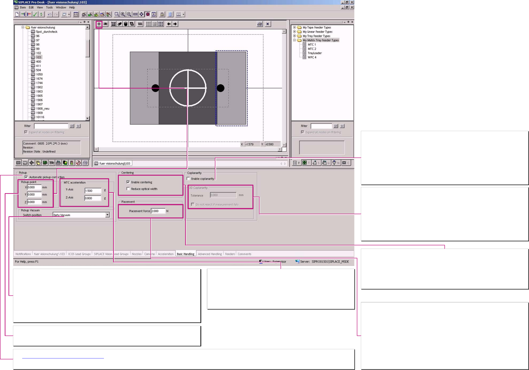
Switch position (the trigger time for vacuum).
Here is defined the operation mode for triggering vacuum on placement heads. (nicht für SC/MC SW 4xx)
Normal vacuum:
at the placement heads the vacuum is activated when the nozzle contacts the component in the feeder.
TWIN, always and at C&P12 / 6 head for nozzles with components bigger 6x6x4mm
Early vacuum:
The vacuum is activated at at C&P12/6 when the LB top is triggered at downward movement for pickup
(at 901/911/925.. already at start downward)..
C&P20-head operates always with early vacuum (at start downward for all comp.smaller than 6x6x4mm)
TWIN-head – never operates with early vacuum.
(Do not mix up with early air kiss in Nozzle programming (valid since SC/MC 604.xx & A364 axis controller))
Nozzle pickup point on component shapes
Here is the contact position⊕ of the nozzle at the component shape to change. This function is not valid for all
versions of station-SW.
Normal nozzle pickup point is identical with the comp. shape reference pos. (comp. shape center)
Acceleration values MTC/WPC4 axes.
Normal acceleration/deceleration
The standard value is for the fastest operation of the machine.
So here is only the possibility to reduce the values:
The acceleration/deceleration value of the Y-axis is valid for the comp. shape –
mean for the respective Level / Tray.
The Value for Z-axis is valid for the respective Tower with the component (MTC).
Automatical Pickup correction
The Pickup position correction for X/Y-pickup position
could be disabled here for exotic components.
The correction is calculated from the position result of the optical centering of the component & the calibration data of the segment. For Melf comp. shape types this function is ‘automatically’ deactivated.
Z-pickup height correction is NOT to disable. (The placement height learning and correction is also not to disable.)
Placement force
The programmed value here is become active ONLY when the respective dynamic profile is
selected in ‚Advanced handling. (The dynamic profile have to be programmed for SC/MC SW 502
and onwards.)
C&P 20 2 N Standard up to 4.5N
C&P 6/12 2 N Standard up to 5 N
TWIN 2 N Standard 1 up to 15N
TWIN-high force 2 N Standard 1 up to 30N
Is for the TWIN (P&P) in ‚Advanced handling’ (see advanced hand. II) a waiting time bottom for
placement combined with this increased placement force so the servo might trigger an ‘over
current error’ (error message I
RMS
). This depend on the thermic stress state of the servo and the
programmed waiting time of 2,5 sec respectively more for increased placement force.
At High Force option the Servo amplifier trigger characteristic is adopted to the motor thermic
characteristic that in normal operation area up to 15 N no error is triggered.
Centering
’Centering’ has to be always active!!!
Only than the component is optically recognized and correct placed.
For internal tests this could be deactivated (all the component cameras are inactive).
Reduced optical width
is only necessary for the Re-export to Unix/Linux LC!
The reduced optical width for the MELF’s is taken from the body shape programming ‚Horizontal
cylinder’.
❑ Enable Coplanarity check
components base on this component shape could be measured with Coplanarity module(Do not
forget to program the sensor).
F- / HF-/ D- machines
have the coplanarity module ILD 2000 / 2200. This module scan with a punctual laser the Gullwing
pins of SO/ QFP/BQFP.
X-machines
may have installed as an option a 3D- coplanarity module. Here scan a laser line the SO/QFP/
BQFP OR ALSO a BGA.
3 D – Coplanarity module
This Option is ONLY to install on an X3 with Box-PC for gantry 3 with TWIN-head.
Tolerance
This tolerance here is the comp. shape-specific tolerance of the balls from a BGA – this terminals
could collapse during soldering process.
This mean;
for a BGA is a component shape specific larger tolerance possible than programmed for the
solder paste thickness in the PCB programming for the QFP/ … comp. shapes.
❑ Do not reject if measurement fails
This setting allows a repeated measurement on the coplanarity module with using the height
measurement results of the measurement for height adjustment.
Component shape
basic handling
A programing overview about process reliability Editon for SIPLACE Pro 5.0 extended for 5.2
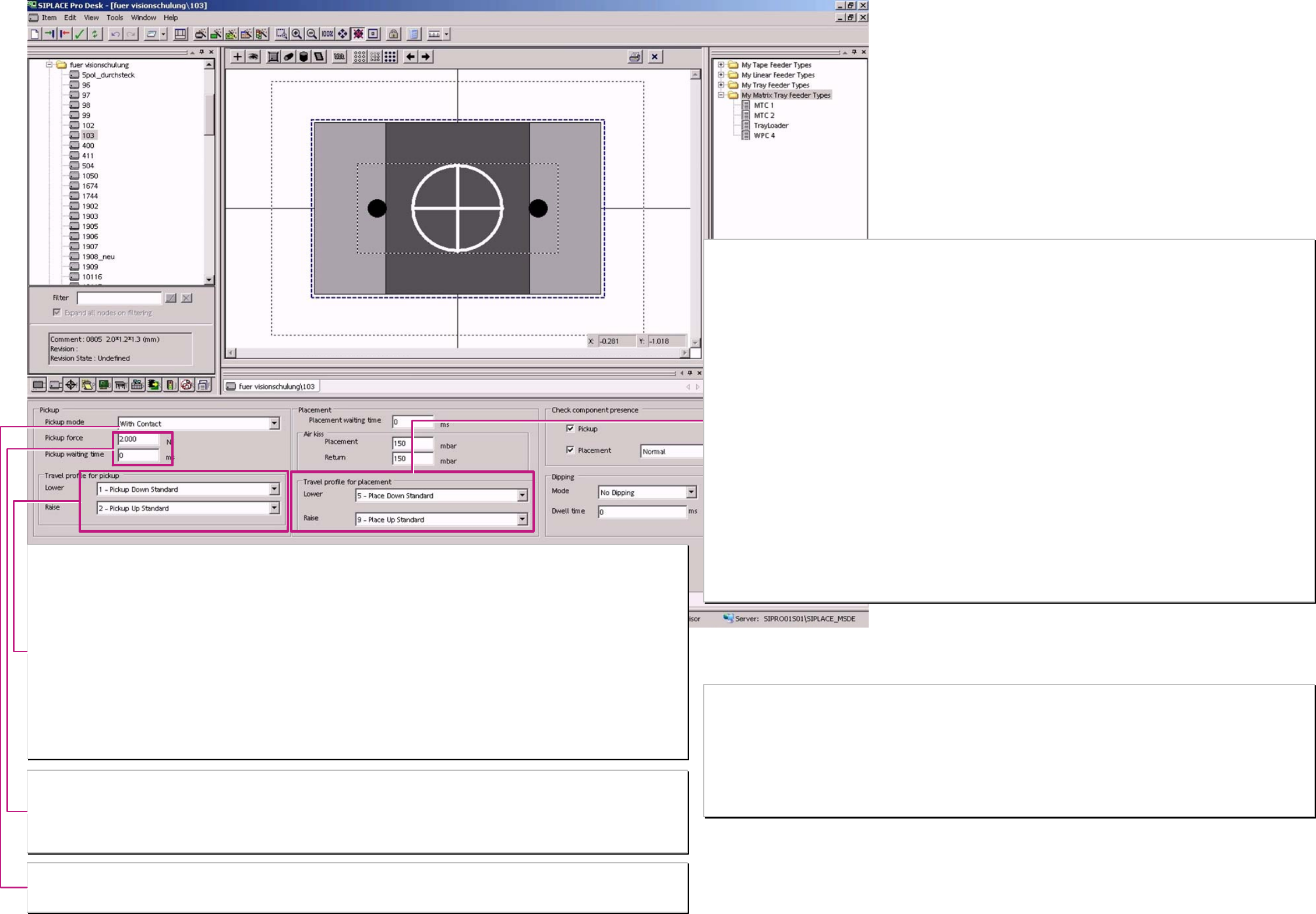
Dynamic profile for Pickup
Here are the special positioning characteristics for the special modes of pickup head cycle set. (Dynamic profile have to be selected for SC/MC SW 502. and
onwards.
Movement downwards:
1 - Downwards Pickup standard: Dynamic profile for Pickup with contact (2N) at comp.. (ca. 15 comp.’s per Lin. feeder to learn pickup height).
17 - Downwards Pickup contactless: Dynamic profile for Pickup without contact (0 N) at comp.. (Learn pickup height at 1
st
access
(of C&P 20/12/6) and than suck at the 2
nd
pickup the comp. ‚to the floating nozzle’.
21 - Downwards Pickup with minimal. force: Dynamic profile for Pickup with TWIN-head and only 1N pickup force.
22 - Downwards Pickup with very low force: Dynamic profile for Pickup with TWIN and 0,5-0,9N –special setting of TWIN head required-
35 – Downwards Pickup 01005 contactless Dynamic profile for Pickup WITHOUT Contact (0N) for 04x02mm (01005) component.
Movement upwards:
1 - Upwards Pickup standard:Dynamic profile start with full acceleration upwards.
3 - Upwards Pickup slow start: Dynamic profile with slow speed for the first ~1mm (~20ms). This cause that the holding force for the
comp. on the nozzle is fully available at upwards acceleration. the comp. wont drop down.
4 - Upwards Pickup creep start: Dynamic profile with slow speed for approx. the first 2 mm (~100ms) required for start upwards at Pickup
from Surftape.
23 - Upwards Pickup with very low force: Dynamic profile for Pickup with TWIN and 0,5-0,9N
-special setting of the TWIN head (pickup & placement force have to be identical).
Pickup force
The Pickup force could be programmed but all values larger 2N are ignored. 1N could be used for TWIN head with Dynamic profile 21. (Pickup force of 0,5-
0,9N are a special construction (SOKO) with a special adjusted TWIN-head)
Waiting time at Pickup
This is used for a very special pickup procedure – the pickup from a Surftape feeder.
This feeder requires approx. 250ms until the reject needle touches the component – than start the pickup procedure on Z-Axis
Pickup mode
“WITH contact“ This standard mean that the head touch on the comp. in feeder with a pickup force of 2 N (except TWIN).
“WITHOUT contact” 0201 that the head learn at the 1
st
access to track the pickup height & at the 2
nd
pickup the comp. is suck. with a distance of ~ 0,1mm
“WITHOUT contact” 01005 same sequence but the Z-axis is more sensible adjusted (necessary? Please test)
Dynamic profiles for Placement
Here are the special positioning characteristics for the force at placement head cycle set.
Movement downwards:
5 - Downward placement standard: Dynamic profile for Placement with standard force (2N) on comp..
(approx. 15 PCB’s per place pos. to learn Placement height). /at 604 the 1
st
PCB than only tiny
corrections for ‚steady height’).
6 - Downward place with slow ‘braking’: Dynamic profile for placement with 2N & slowly movement in pos. (~1mm) e.g. for BGA balls in
filling mat.
7 - Downward placement w. place.force: Dynamic profile for place with 3-5N (TWIN 3-10N).
For large contact areas in (dried) solder paste.
8 - Downward place w.place force&slow ‚braking’: Dynamic profile combination of ’7' & ’6'. e.g. for ~1mm high centering pins with increased force.
25- Downward place w. very high force: Dynamic profile for Place. with TWIN-head with 11-15N. (26 same Force with slow move in pos.)
26- at Option HIGH FORCE: Dynamic profile for Placement with HIGH FORCE TWIN-head with 16-30N.
27- Downward place w. minimal Force: Dynamic profile for Place with TWIN & with 1N. same red. force like at pickup
28- Downward place w. minimal Force &slow ‚braking’: same Force like with profile 27 but additional with slow movement in position.
29- Downward place w. very low Force Dynamic profile for Place w. TWIN & with 0.5-0.9N special arranged TWIN
(former Low force nozzle).
30- Downward place w. very low Force & slow brak. Dynamic profile for Place w. TWIN with 0.5-0.9N special arranged TWIN & with slow
move into position.
31- Downward place smooth Dynamic profile for Place with C&P for very sensitive 06x03mm(0201) components refer to 2N
32- Downward place smooth for Centering Pin Dynamic profile (for Place with TWIN for comp. with center. pin & place. force 2N) not realized
up to 604/701??
33 - Downward place 01005 Dynamic profile for Place of 04x02mm (01005) comp.’s with ’adopted force [34 is 33 & w slow
move in pos.]
Movement upwards:
9 - Upwards Placement standard: Dynamic profile start with full acceleration Upwards.
10 - Upwards Place slow start: Dynamic profile with slow speed for the first ~1mm (~20ms). This cause that the comp. is not
taken from the PCB with the nozzle at Upwards acceleration if the holding force on the PCB is
extremely low
24 - Upwards Placement with very low Force: Dynamic profile for Placement with TWIN if the placement force of 0,5-0,9N have to be used.
-special setting of the TWIN head (pickup & placement force than identical) (see 29/30 &22).
Component shape
Advanced Handling I
Placement process 0201 (see body) requires
Contact less Pickup with Dynamic profile 17 & fitting nozzles 906/ 902 & comp.-Sensoroption on C&P12 respectively
Contact less Pickup with Dynamic profile 17 & fitting nozzles 1006/ ... & comp.-Sensor C&P20
Contact less Pickup works only out from the special ...0201 S feeder or with insert of the spacers below the paper tapes
Placement process 01005 (see body) requires
Contact less Pickup with Dynamic profile 35 (17) & fitting nozzles 905 and special sleeve and feeder & comp.-Sensor replacement function on
C&P12 of D1/D1 or D4 machine respectively
Contact less Pickup with Dynamic profile 35 & fitting nozzles 1006/ ... & comp.-Sensor C&P20
Contact less Pickup works only with insert of the spacers below the paper tapes
Are this options seperately selected so any componentshape could be processed with placement functions for 0201 placement process.
A programing overview about process reliability Editon for SIPLACE Pro 5.0 extended for 5.2
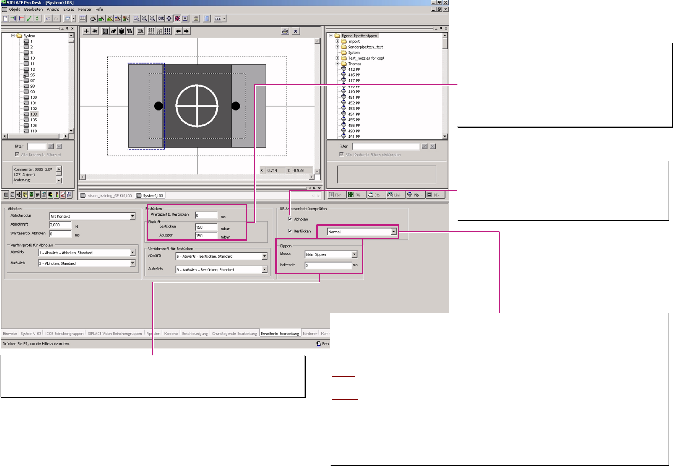
Waiting time at placement
To guarantee a floating of conductive glue below the DIE’s or drying of flux at placement it is useful
to program several x00ms waiting time down at placement.
Air kiss at placement (or return component)
The electronically of vacuum and air kiss generation allow to set the air pressure (150 default) at
placement and control in a closed loop.
Achieving 80% (typical) the machine recognize that the C&P20 or the TWIN-head has placed the
component..
The C&P 12/6 heads use this values for a time controlled operating time of the.air kiss solenoid (No
time gain in pickup)
1-50 air kiss solenoid OFF when the valve drive is started (not useful)
51-150 air kiss solenoid OFF when valve drive turned 90° (standard)
151-255 air kiss solenoid OFF when valve drive turned 180° or Z-axis come to LB top.
Component presence tests
The operation mode for the comp. presence test (presence check or height check) is defined here.
❑ Pickup (after)
Here the machine checks if a component was successfully picked up.
If it fails the comp. is immediately re-picked possibly after reject of the 1
st
comp.
This mode is permanent active for the comp. sensor at C&P20 head.
❑ Placement (before)
Here the machine checks if the component is on the nozzle before placement.
If it fails the placement head circle with this segment is not started or interrupted.
Kind of component presence test
with this 5 kind of component presence tests are the placement head specific component tests are programmed.
The TWIN-head could only test with Vacuum check so it ignore other programmings. Same operation for the C&P 6.
The C&P12 head work according optional equipment with vacuum or with comp. Sensor. C&P12 comp. height check for comp.’s on nozzle longer 12,5mm
and comp. height smaller approx 4,5mm. The C&P20 head work only with comp. sensor.
Normal
TWIN: Vacuum / C&P6. Vacuum / C&P12: Vacuum or C/P12 comp.sensor option: Vacuum / C&P20: comp. presence check
C&P12 only vacuum based comp. presence test (just the same TWIN & C&P 6).
Attention; for 902/900/925 and similar tiny nozzles NO vacuum test is possible to execute!
Such nozzle types require for 0603mm (0201) placement normally a comp. sensor at C&P12-head!)
Advanced
TWIN: Vacuum / C&P6: Vacuum / C&P12: Vacuum C/P12 comp.sensor option: Vac.&comp. / C&P20: comp. presence check
C&P12 comp.sensor option: only vacuum based comp. presence test at pickup; before placement also comp. sensor based presence check
Vacuum based presence test for TWIN& C&P6 C&P20 comp. sensor based comp. presence check no vacuum test for any type of nozzle.
NO vacuum
TWIN Vacuum / C&P6 ---- / C&P12 ---- C/P12 comp.sensor option: comp.pres.check / C&P20 comp. pres. check
C&P6/12 without comp.sensor NO comp. presence test. C&P12 with comp.sensor option: comp. Presence check before placement only! C&P20 comp.
sensor based comp. presence check
Comp. sensor – thickness check
TWIN Vacuum / C&P6 Vacuum / C&P12 Vacuum C/P12 comp.s. option: Vac.& comp.height check / C&P20 comp. height check
C&P12 with comp. sensor opt. vacuum test after pickup : before placement comp. height check on nozzles long & comp. height low enough . C&P20 comp.
sensor based comp. presence check.
Comp. sensor – thickness check NO vacuum
TWIN Vacuum / C&P6 ----? / C&P12 ---- C/P12 comp.sensor option: comp. height check / C&P20 comp. height check
C&P12 w. comp.sensor opt. No presence test after pickup : before placement comp. height check on nozzles long & comp. height low enough
C&P20 comp sensor based comp. height of all comp. on all nozzles.
Dipping (BGA/ FlipChip into flux)
Was Dipping selected each C&P12/6 or Twin head could dip the comp.in the Dip unit S-table (round disk) or in the Linear Dip Unit (X-table).
Dipping Vision Dipping is done before Vision. With 605 SIPLACE Vision is able to inspect dipped terminals.
Vision Dipping Dipping is done after Vision. Danger comp. may move during dipping take care on nozzle contact
Dwell time
Several x00ms remain the BGA/FlipChip comp. in flux with defined adjusted flux material thickness (40-50% Ball radius).
Component shape
Advanced Handling
A programing overview about process reliability Editon for SIPLACE Pro 5.0 extended for 5.2