SIPLACE Vision Customer_en.pdf - 第202页
Default feeder for the component shape. Here is the default feeder of the component shape def ined. Is a feeder allocated to a component so this one has priority for use. X-Feeder: This feeder series is the only one fast…
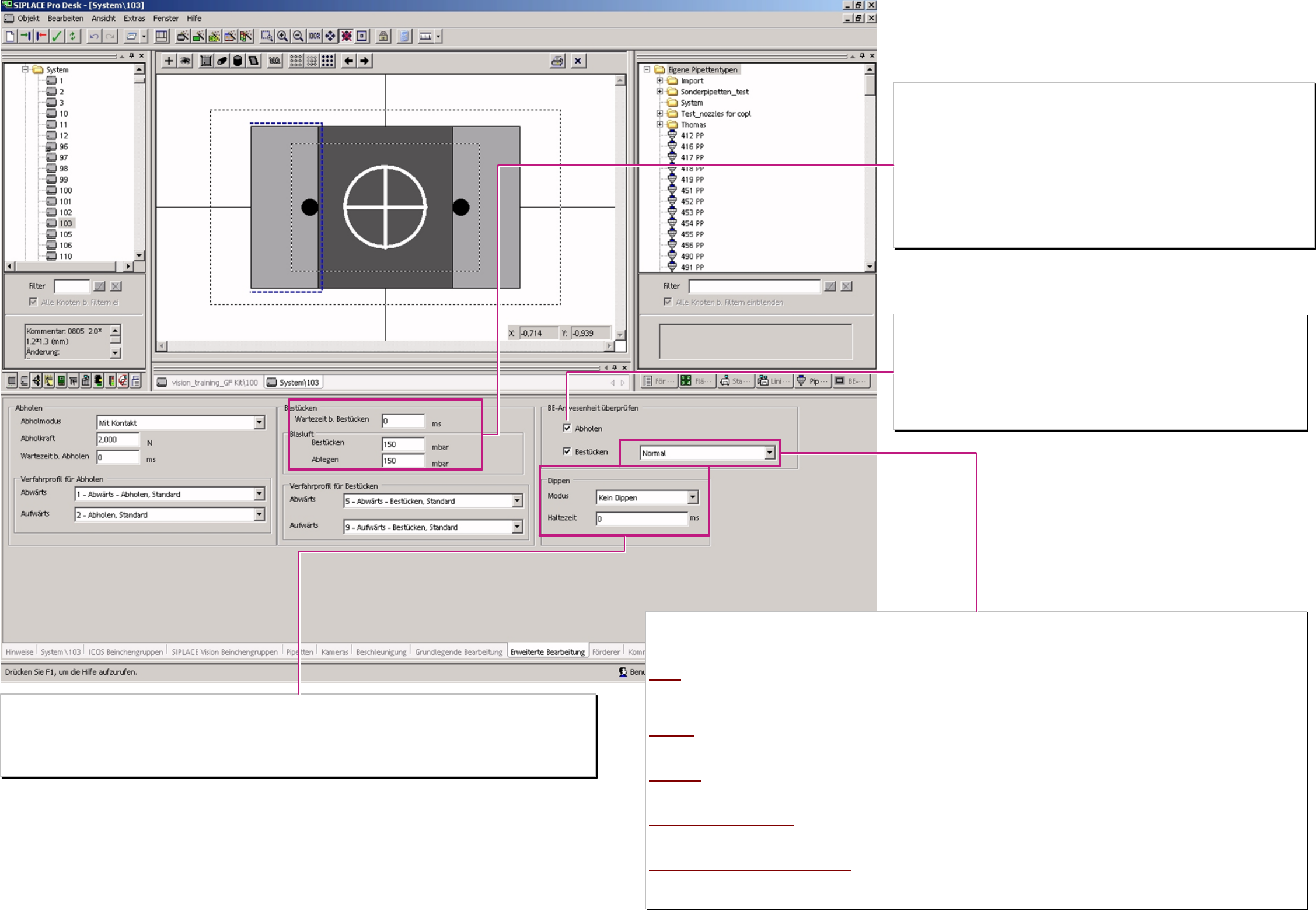
Waiting time at placement
To guarantee a floating of conductive glue below the DIE’s or drying of flux at placement it is useful
to program several x00ms waiting time down at placement.
Air kiss at placement (or return component)
The electronically of vacuum and air kiss generation allow to set the air pressure (150 default) at
placement and control in a closed loop.
Achieving 80% (typical) the machine recognize that the C&P20 or the TWIN-head has placed the
component..
The C&P 12/6 heads use this values for a time controlled operating time of the.air kiss solenoid (No
time gain in pickup)
1-50 air kiss solenoid OFF when the valve drive is started (not useful)
51-150 air kiss solenoid OFF when valve drive turned 90° (standard)
151-255 air kiss solenoid OFF when valve drive turned 180° or Z-axis come to LB top.
Component presence tests
The operation mode for the comp. presence test (presence check or height check) is defined here.
❑ Pickup (after)
Here the machine checks if a component was successfully picked up.
If it fails the comp. is immediately re-picked possibly after reject of the 1
st
comp.
This mode is permanent active for the comp. sensor at C&P20 head.
❑ Placement (before)
Here the machine checks if the component is on the nozzle before placement.
If it fails the placement head circle with this segment is not started or interrupted.
Kind of component presence test
with this 5 kind of component presence tests are the placement head specific component tests are programmed.
The TWIN-head could only test with Vacuum check so it ignore other programmings. Same operation for the C&P 6.
The C&P12 head work according optional equipment with vacuum or with comp. Sensor. C&P12 comp. height check for comp.’s on nozzle longer 12,5mm
and comp. height smaller approx 4,5mm. The C&P20 head work only with comp. sensor.
Normal
TWIN: Vacuum / C&P6. Vacuum / C&P12: Vacuum or C/P12 comp.sensor option: Vacuum / C&P20: comp. presence check
C&P12 only vacuum based comp. presence test (just the same TWIN & C&P 6).
Attention; for 902/900/925 and similar tiny nozzles NO vacuum test is possible to execute!
Such nozzle types require for 0603mm (0201) placement normally a comp. sensor at C&P12-head!)
Advanced
TWIN: Vacuum / C&P6: Vacuum / C&P12: Vacuum C/P12 comp.sensor option: Vac.&comp. / C&P20: comp. presence check
C&P12 comp.sensor option: only vacuum based comp. presence test at pickup; before placement also comp. sensor based presence check
Vacuum based presence test for TWIN& C&P6 C&P20 comp. sensor based comp. presence check no vacuum test for any type of nozzle.
NO vacuum
TWIN Vacuum / C&P6 ---- / C&P12 ---- C/P12 comp.sensor option: comp.pres.check / C&P20 comp. pres. check
C&P6/12 without comp.sensor NO comp. presence test. C&P12 with comp.sensor option: comp. Presence check before placement only! C&P20 comp.
sensor based comp. presence check
Comp. sensor – thickness check
TWIN Vacuum / C&P6 Vacuum / C&P12 Vacuum C/P12 comp.s. option: Vac.& comp.height check / C&P20 comp. height check
C&P12 with comp. sensor opt. vacuum test after pickup : before placement comp. height check on nozzles long & comp. height low enough . C&P20 comp.
sensor based comp. presence check.
Comp. sensor – thickness check NO vacuum
TWIN Vacuum / C&P6 ----? / C&P12 ---- C/P12 comp.sensor option: comp. height check / C&P20 comp. height check
C&P12 w. comp.sensor opt. No presence test after pickup : before placement comp. height check on nozzles long & comp. height low enough
C&P20 comp sensor based comp. height of all comp. on all nozzles.
Dipping (BGA/ FlipChip into flux)
Was Dipping selected each C&P12/6 or Twin head could dip the comp.in the Dip unit S-table (round disk) or in the Linear Dip Unit (X-table).
Dipping Vision Dipping is done before Vision. With 605 SIPLACE Vision is able to inspect dipped terminals.
Vision Dipping Dipping is done after Vision. Danger comp. may move during dipping take care on nozzle contact
Dwell time
Several x00ms remain the BGA/FlipChip comp. in flux with defined adjusted flux material thickness (40-50% Ball radius).
Component shape
Advanced Handling
A programing overview about process reliability Editon for SIPLACE Pro 5.0 extended for 5.2
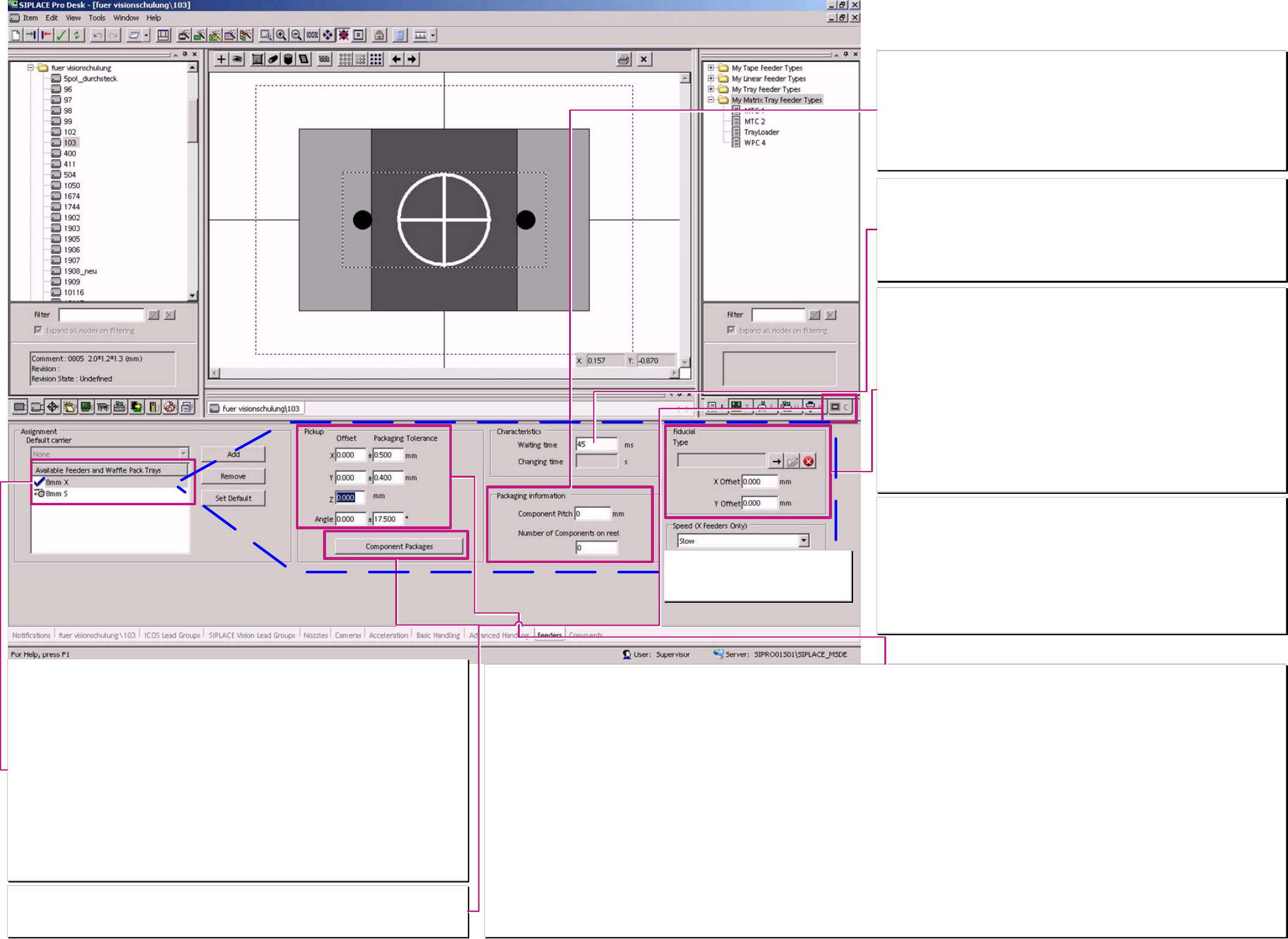
Default feeder for the component shape.
Here is the default feeder of the component shape defined. Is a feeder allocated to a component so this
one has priority for use.
X-Feeder:
This feeder series is the only one fast and precise enough feeding the components for the C&P 20 head.
All types of tape, and linear feeders (Stick magazines) are available since 2007.
S-Feeder:
need on X-machines comp. tables with the mechanical, electrical S-Feeder interface.
Blue marking tick
label the default feeder of the component shape. This is to program ‘Set default’ button if more than one
feeder is available in program.
Unfortunately, you could not select default feeder for the two series, S- and X- configuration, separately.
EL Electrical Feeder:
could be continually used up to S27 or F5HM machines.
Stick magazines (4,5) / 9,5 / 10 / 15 / 30mm:
requires the linear – vibration feeder base – available for S and X- comp. table.
Other special feeder:
see therefore feeder programming over view or the respective user manual.
Component packaging:
Here is a special programming for a customized feeder allocated to a basic feeder type:
Pickup offset, Pickup tolerance, Pickup angle, Waiting time pickup could be reused calling this
‘customized feeder name.
Pickup offset
This pickup offset at X/Y orientation is considered at set up optimization and at the pickup with the placement head. For large comp. shapes which come close to the size of the field of view
this offset influence the calculation the max. possible pickup tolerance.
Moving the nozzle contact position change also the pickup offset because it is automatically considered in the feeder pickup position at SC/MC 505.xx and 6xx.
Pickup tolerance
The Pickup offset should not influence essentially the placement shadow of tiny, of identical high components. Therefore it is recommended that the material thickness of the nozzle is the
maximal allowed exceed. At the easiest this is to recognize at the nozzle programming. Measure this material thickness with 2 Cursor positions an the nozzle extent and at the vacuum
channel. To keep the reject rate in acceptable low range the pickup tolerance should not be programmed essentially lower than 0,2mm.
For larger components you could check the varity of the component position in the tape or feeder
Please Note for Comp. As wide as camera field of view: SIPLACE Pro use only 1 Pickup tolerance (the maximum one) for the calculation of overall Component shape size!
Z-offset
Is here entered a positive Z-Offset so the machine expect that the comp. higher and calculates for a dynamic profile that move not so far down with full acceleration / speed.
Pickup offset angle
This angle value is considered in the set up optimization. Enter here the pickup angle in 90° steps if the component position in the feeder deviates from the comp. shape 0° programming
position.
Do not try to correct the pickup error of a thoughtless pickup angle programming with ’Orientation’. This lead to polarity errors on symmetrical integrated circuit comp. shapes respectively a
remarkable time lost because of multiple measurements.
Pickup tolerance angle
This tolerance influence mainly the measurement time at Shield recognition if it is set to values above 10°. Than the search algorithms for the large searching area of the corner recognition
last extremely long and influence the placement rate.
Please consider for connectors that this angle tolerance is programmed with an respective large Y-pickup tolerance. Otherwise some features along the long X-dimension came out of the
search range of the Y-direction – this lead to the Error message ‘search area too small –not all features found’.
Characteristics
Waiting time
Waiting time for the comp. transport at linear feeder – as long as this waiting time runs no
pickup access is done to this feeder.
The set up optimiztion consider this time also for tape feeder allthough the station use a type
specific fix waiting time.
See also the Feeder chart – with module images and short descriptions.
---.
Packaging information
previously they where used for filling level check and Setup center. Now this is transmitted to
X-feeder and since 603 to S-feeder for feeder control.
Component Pitch
is the transport step of the components in the tape.
The programmed pitch sent for SIPLACE Pro is used at the X- and the S-Feeder for default
pitch. The operator could change this on the station if required.
Number of components on the reel
Information for filling level check and Setup center.
Fiducial (feeder position recognition fiducial)
Here are NO programmings or adjustments necessary!!!
for X- feeder
is the comp. length 1,1mm (0402) or shorter so is from the comp. shapes data a comp. pocket
geometry created. This is used for optical feeder position recognition at 8mm X-feeder of the
respective track at the first scheduling of the production recipe.
for S-feeder
Feeder pos. recognition with pocket fiducial is used for 0201 3x8mm S feeder or
3x 8mm SL feeder and for components which are 0,6mm (0201) or shorter.
Feeder pos. recognition with feeder fiducial is used for 0201 3x8mm S feeder or
3x 8mm SL Feeder and if the comp. length exceeds 0,6mm but the comp.-width is smaller
0,8mm (0603).
Feeder pos. recognition with feeder fiducial is used for 3x 8 mm Standard and 2x8mm S-
feeder if the comp. width is 0,8mm or smaller.
If S- or X-feeder have larger components NO feeder position recognition is executed.
Component shape Feeder
X- feeder speed
Here 3 different transport speed levels for
the X- Feeder could be selected & and
scheduled to the feeder.
X/Y-Pickup tolerance calculated value set by SIPLACE Pro at programming:
If one of the dimensions X
Nom
or Y
Nom
is
smaller 2,0mm the pickup tol. X/Y 0,5mm is set
smaller 5,0mm & both are larger 2,0 mm the pickup tol. X/Y 0,7mm is set
smaller 9,0mm & both are larger 5,0 mm the pickup tol. X/Y 0,95mm is set
smaller 35,0mm & both are larger 9,0 mm the pickup tol. X/Y 1,3mm is set
If both dimensions X
Nom
and Y
Nom
are
larger 35,0 mm the pickup tol. X/Y 1,8mm is set.
The ‘calculated default’-pickup angle tolerance is defined from SIPLACE Pro for the same
dimension steps.
A programing overview about process reliability Editon for SIPLACE Pro 5.0 extended for 5.2
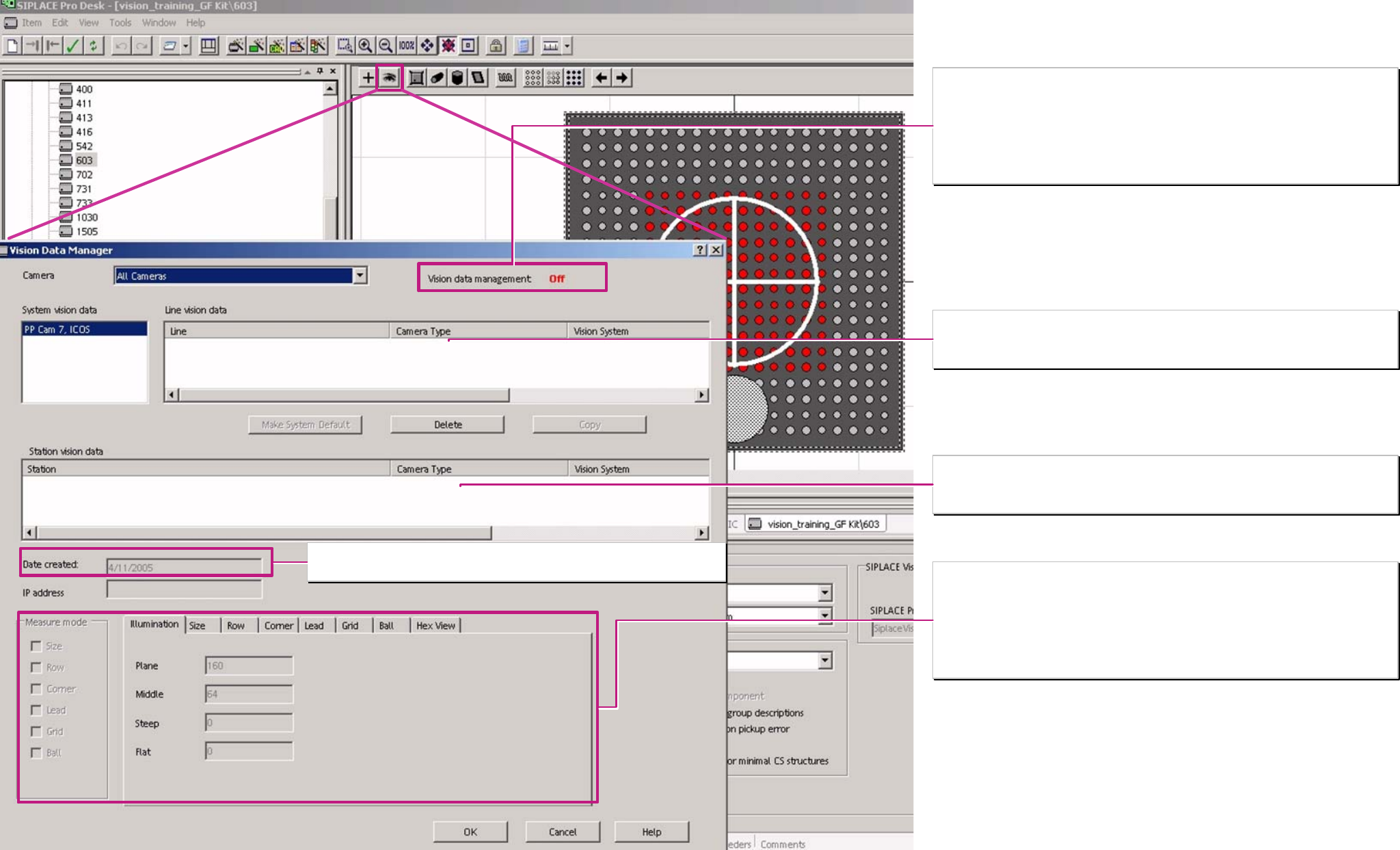
Vision data management OFF
Is Vision Data Management disabled so you can see ONLY the teaching data of the ’system
camera’ and you could delete them to reset to standard recognition.
Vision data management ON
Is Vision Dat Management enabled so you can see the teaching data of the cameras, which
are allocated for the line or the station.
It is possible to allocate the system camera data only for a line or a station.
Component shape Vision data
Creating date or last date of changing
For SIPLACE Vision cameras is this the ONLY information which is shown in VDM!!
Illumination and Parameter settings to the different measurement methods
For ICOS cameras are the parameter for optical centering shown if only one parameter was
changed and saved at teaching.
(this is not valid for Ball centering steps used for BGA recognition.)
For SIPLACE Vision cameras you see only the last date of changing.
Component camera data for the optical centering of this component shape (only with Vision
data management ON) allocated to a certain line.
It might be a ICOS camera as well as a SIPLACE Vision camera
Component camera data for the optical centering of this component shape (only with Vision
data management ON) allocated to a certain station.
It might be a ICOS camera as well as a SIPLACE Vision camera
A programing overview about process reliability Editon for SIPLACE Pro 5.0 extended for 5.2