SIPLACE Vision Customer_en.pdf - 第32页
User Interface Error Analysis Logs Enabling Vision Log Recording S tudent Guide SIPLACE V ision (Customer) User Interface Edition 12/2008 EN 32 4.10 Error Analysis Logs Note: These functions may ONL Y be acc essed by us …
User Interface
Station Interface for Teaching Component Shapes Setting the Algorithms
Student Guide SIPLACE Vision (Customer)
Edition 12/2008 EN User Interface
31
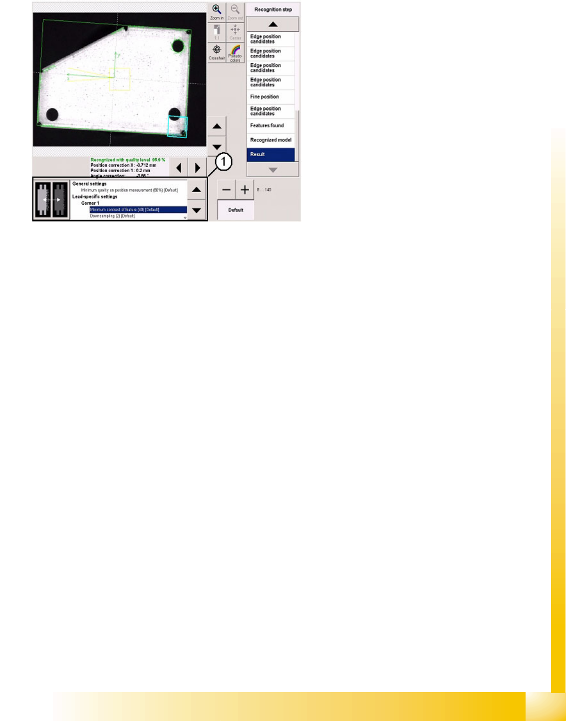
4.9 Setting the Algorithms
Use the list on the right to select and adjust the
individual measurement steps.
Settings are only possible here in exceptional
cases e.g. when analyzing images with inverted
colors.
1. The algorithm thresholds can be set in the
window shown. The recognition steps can be
altered independently of these.
The algorithm thresholds apply for the entire
position recognition function and for the
respective group descriptions.
User Interface
Error Analysis Logs Enabling Vision Log Recording
Student Guide SIPLACE Vision (Customer)
User Interface Edition 12/2008 EN
32
4.10 Error Analysis Logs
Note: These functions may ONLY be accessed by users with service technician privileges!
4.10.1 Enabling Vision Log Recording
In the pulldown menu View, the user can enable recording of an analysis and result log for Vision
centering and the related error localization procedure. To access the Vision menu, select the operating
mode Setter.
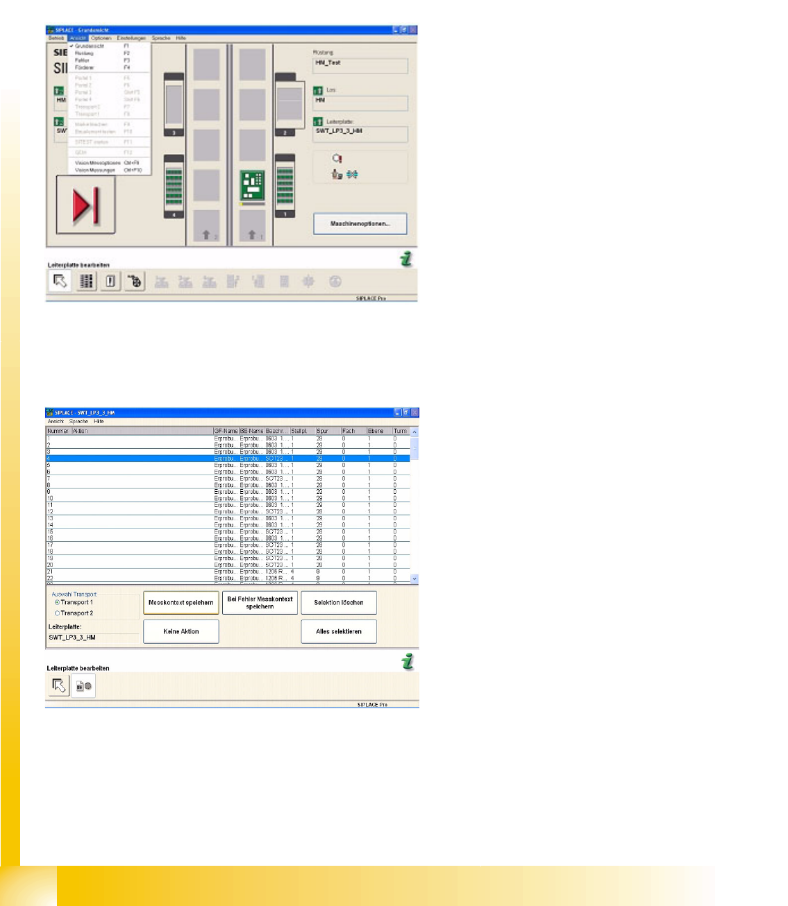
4.10.1.1 Vision Measurement Options
Use this menu to set the Report of measurement results for selected components.
Items in the pulldown menu View:
Vision measuring option – can also be opened
with CTRL + F9.
Vision measurement - can also be opened
with CTRL + F10.
Once a component has been selected in the list,
the buttons will be enabled.
Save measurement context saves the analysis
and results log for this component shape.
No Activity is the default value (no recording is
performed).
Error Save measurement result saves the
centering errors in the analysis and results log
for this component shape (see also the
attached error log).
Delete Selection or Select All are function buttons
for easier selection of the component shape.
User Interface
Enabling Vision Log Recording Error Analysis Logs
Student Guide SIPLACE Vision (Customer)
Edition 12/2008 EN User Interface
33
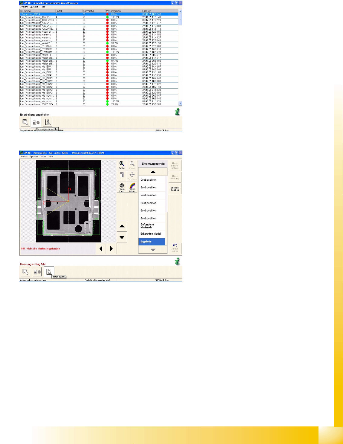
4.10.1.2 Vision Measurement
The individual steps and corresponding results for the optical centering recorded in this error example
can be examined analogous to the analysis surface.
The presentation in the pseudo-colors figure shows the areas of contrast on the component.
The crosshairs show the component pickup offset. Use the zoom function to view details. Each
measurement step and the corresponding result can be viewed in detail in the recognition step menu.
See also:
J
4.10.1.1 Vision Measurement Options [
J
32]
The measurement log shown here is issued when
enabled in Measurement options and can be
called up at Vision measurements, when an error
occurs.
In the menu Display Measurement the individual
measurement steps are shown for the selected
components.
The analysis log in this example shows incorrect
programming of the vectors for corner recognition:
the system tries to locate the light-colored Shield
surfaces to the left of the respective corner
recognition vector.