SIPLACE Vision Customer_en.pdf - 第57页
Component Shapes Moulded (Injection Moulded) Components (for Tantal Capacitor s) Specific Component Shapes S tudent Guide SIPLACE Vision (Customer) Edition 12/2008 EN Component Shapes 57 Special features Component shap…
Component Shapes
Specific Component Shapes Moulded (Injection Moulded) Components (for Tantal Capacitors)
Student Guide SIPLACE Vision (Customer)
Component Shapes Edition 12/2008 EN
56
When converting from previous CS datasets (ICOS), MELF component shapes, which have been
programmed as PDC, will not be automatically assigned. In this case, reprogram the CS with leads.
Due to the very simple programming method, involving body size with attached wraparound leads, NO
component shape wizard is offered for MELF component shapes.
ICOS descriptions accept a CO width reduction between 60 and 100% in the measurement algorithm.
In order to cover as many COs as possible with the CS description, use a relatively high width tolerance.
5.3.5 Moulded (Injection Moulded) Components (for Tantal Capacitors)
JEDEC description
JEDEC description
Lead description
Body description: rectangular.
The Z height of the body determines the measurable height
in the CO sensors.
The X/Y body dimensions determine the field of vision, the
Region of Interest.
This also determines the outer starting edge of the
Wraparound leads.
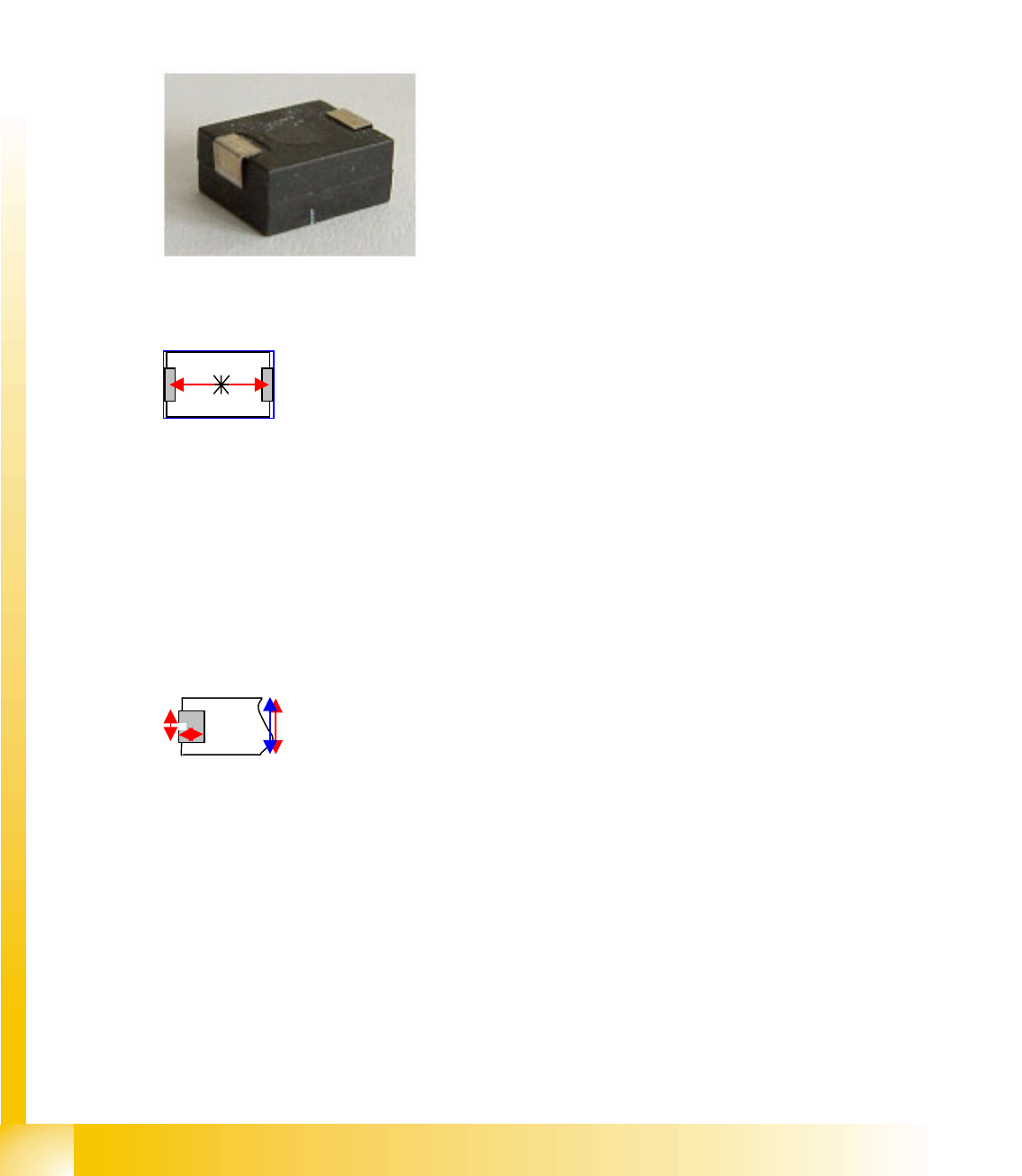
This component consists of two lead groups, each with one
lead.
The leads in the two groups must be identical!
The leads are inside the body surface.
In the case of this component, the leads are understood to
begin where the body begins, meaning that a group offset
does not need to be programmed. After optical centering,
the distance between the leads and the center (body
center) is measured and used for the placement
coordinates.
This component shape has so-called Wraparound leads,
which are wrapped around the component body, hence the
name Wraparound.
This defines the lead direction: towards the CO center. The
lead description requires definition of the lead length and
width.
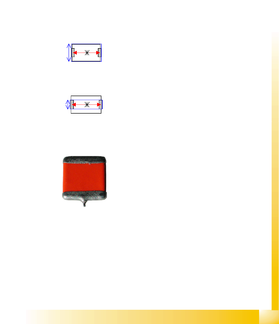
The lead width is greater than the length, although they are
narrower than the body itself.
The lead length must not exceed 50 percent of the body
length (this would cause a short circuit!).
Make sure that no notches are programmed in the lead
surface (positive pole recognition).
Notches or dark areas in the leads could be interpreted as
"noise" in the lead surface of this CS. Alternatively, the CO
can be defined as a nonstandard component with notches.
Component Shapes
Moulded (Injection Moulded) Components (for Tantal Capacitors) Specific Component Shapes
Student Guide SIPLACE Vision (Customer)
Edition 12/2008 EN Component Shapes
57
Special features
Component shape recognition in SIPLACE Vision is fully independent of the body color. In contrast,
ICOS systems may need to store multiple CSs of the same body size because the body color is
different.
In the measurement algorithm of the molded components, you can alternatively measure the body
dimensions
LxB (1) or width, determined by the lead LxBp (2), in order to recognize the different colored body of
the component with one component shape.
The inspection mode can be deactivated but should remain active.
Attention: if the component height is the same as the lead width, components which are taken up in
an upright position will not be recognized and will then be rejected.
Older Tantal shapes have another special feature:
Observe the following in this case:
When light-colored body material is used, the injection edges all round the component (halfway up
the component) will be shown. In this case, allow for increased width and length tolerances.
If the component height is identical with the lead width, Pick-up component in sideways rotation will
not be recognized (currently not supported).
The function 'Stop at Pickup Error' should be enabled, so that the operator can remove components
which were not picked up from the tape, to avoid sparks being created if these are cut.
Electrolytic capacitors (ECVs) are automatically classified as Moulded, since the body description
Vertical cylinder, round is not available.
Joint datasets with ICOS data possible!
Dimension check 1
LxW L=body length, W=body width
Alternative 2
LxWW L=body length, WW=body width
Previous Tantal components had a soldered nib on one lead.
These components are no longer in regular use. However, if
they should occur, they will be defined as CHIP components.
Component Shapes
Specific Component Shapes Optical Recognition and Evaluation of Unleaded COs
Student Guide SIPLACE Vision (Customer)
Component Shapes Edition 12/2008 EN
58
Due to the very simple programming method, involving body size with attached wraparound leads, NO
component shape wizard is offered for molded component shapes.
SW extension: FaceDown recognition can be programmed and used from SC 702.01 SW (SIPLACE
Vision 4.1).
Lead length inspection can be programmed and used for molded component shapes from SC 702. (See:
New Siplace Vision Functions 702).
5.3.6 Optical Recognition and Evaluation of Unleaded COs
Based on the example of a molded CO (Tantal capacitor)…
A leaded CO is processed with the following measurement steps:
1. Position recognition through determination of the following measurement values:
1. Coarse position - quick determination of component position.
2. Coarse angle - quick determination of angle.
3. Fine angle - exact measurement of angle.
4. Fine position - exact measurement of component position.
2. Component inspection via dimension check.
If the specified tolerances are exceeded, the component concerned will not be placed.
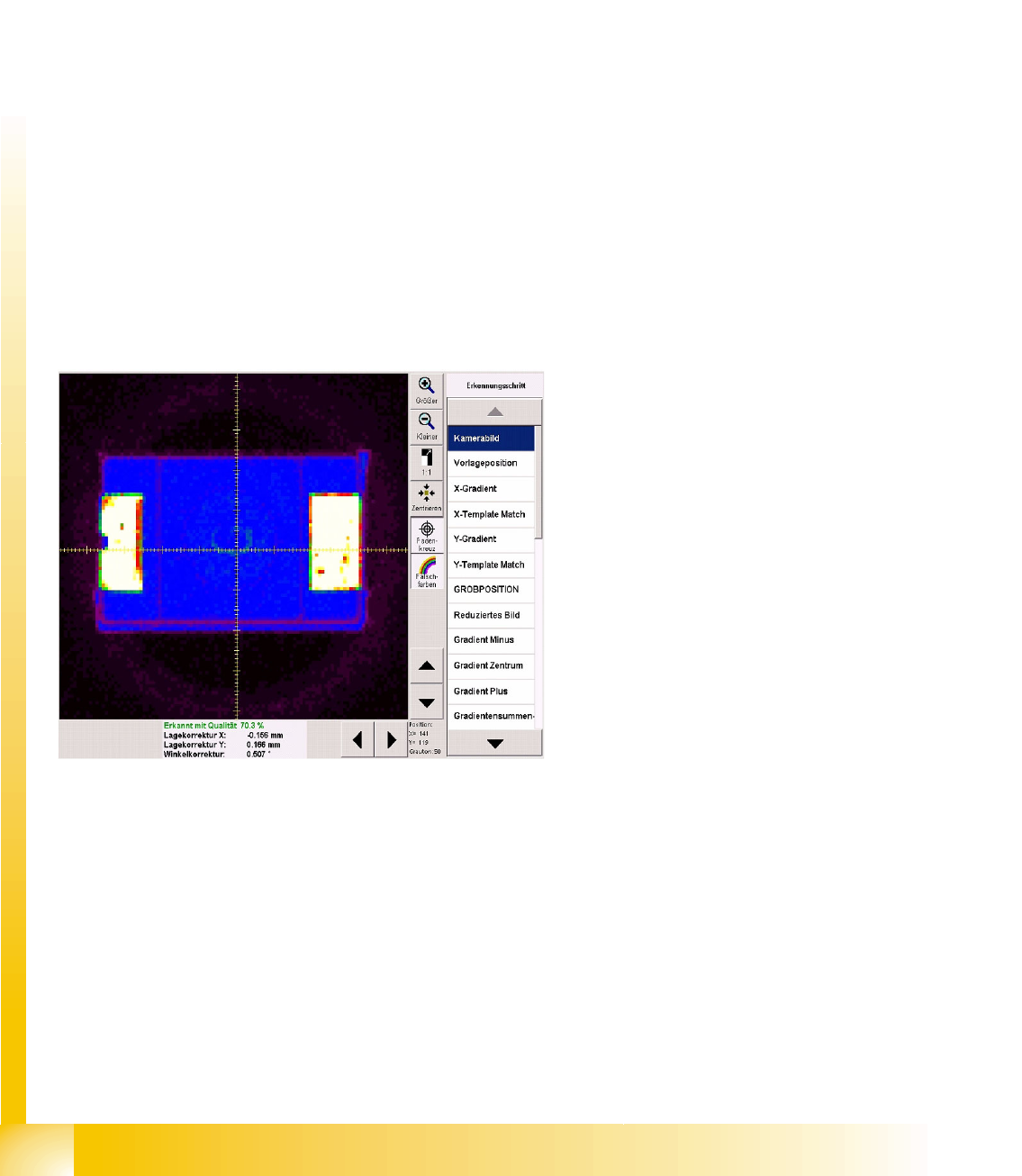
5.3.6.1 Position Determination for Unleaded COs
Diagram unprocessed camera image
The brightness and contrast can be assessed
more easily by switching over to pseudo-color
display:
In this example, White shows the CO
connection points for the Wraparound leads.
Blue shows the dark CO plastic body; the
darker edges are displayed in purple.
Purple/black shows the nozzle/segment
background.
The pickup accuracy can also be recognized on
the camera image and in the measurement
results:
The pickup accuracy is higher the more
accurately the CO center matches the camera
center or the lower the position correction factor is
(X, Y).
Various measurement steps are performed,
depending on the CO type. The individual steps
are explained in the following example.