SIPLACE Vision Customer_en.pdf - 第94页
Component Shapes Specific Component Shapes Shields S tudent Guide SIPLACE V ision (Customer) Component Shapes Edition 12/2008 EN 94 Filter type 250, for poor edge quality; As in the case of the default setting, sever…
Component Shapes
Shields Specific Component Shapes
Student Guide SIPLACE Vision (Customer)
Edition 12/2008 EN Component Shapes
93
5.3.11.2 Special Features for Shields
Shields are sheet metal with curved edges in a wide range of body shapes, some with openings/
holes drilled through; inner and outer corners and various opening angles.
The evaluation times increase with the programmed angle tolerances.
Various corner filters: four corner filter types are possible, depending on the different shield edges
used.
Filter type 248 e.g. for edge springs;
Default setting: Several position candidates
are permitted for each edge, although each
candidate must be above the gradient
threshold. Each edge is also subjected to an
additional scan. This singles out poor quality
edges, primarily candidates caused by
springs.
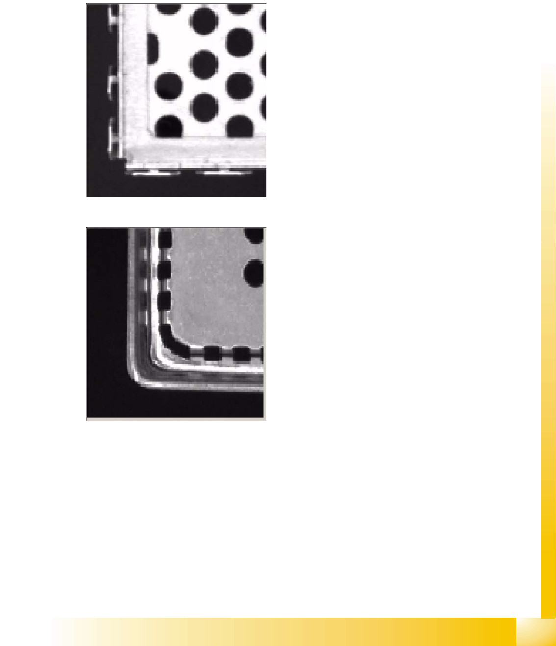
Filter type 249, for good edge quality;
Outer edge: Always takes the outermost
position (as seen when looking from outside
the component) above the gradient threshold
(in the case of double edges, caused by
indentations in the Shield and steep
illumination). The system only considers
edges which are within the yellow search
frame.
Component Shapes
Specific Component Shapes Shields
Student Guide SIPLACE Vision (Customer)
Component Shapes Edition 12/2008 EN
94
Filter type 250, for poor edge quality;
As in the case of the default setting, several
candidates are possible. However, in this
case, an additional scan is not performed
(suitable for Shields with poor edge quality.
The edge in the diagram shown has both bright
and dark points).
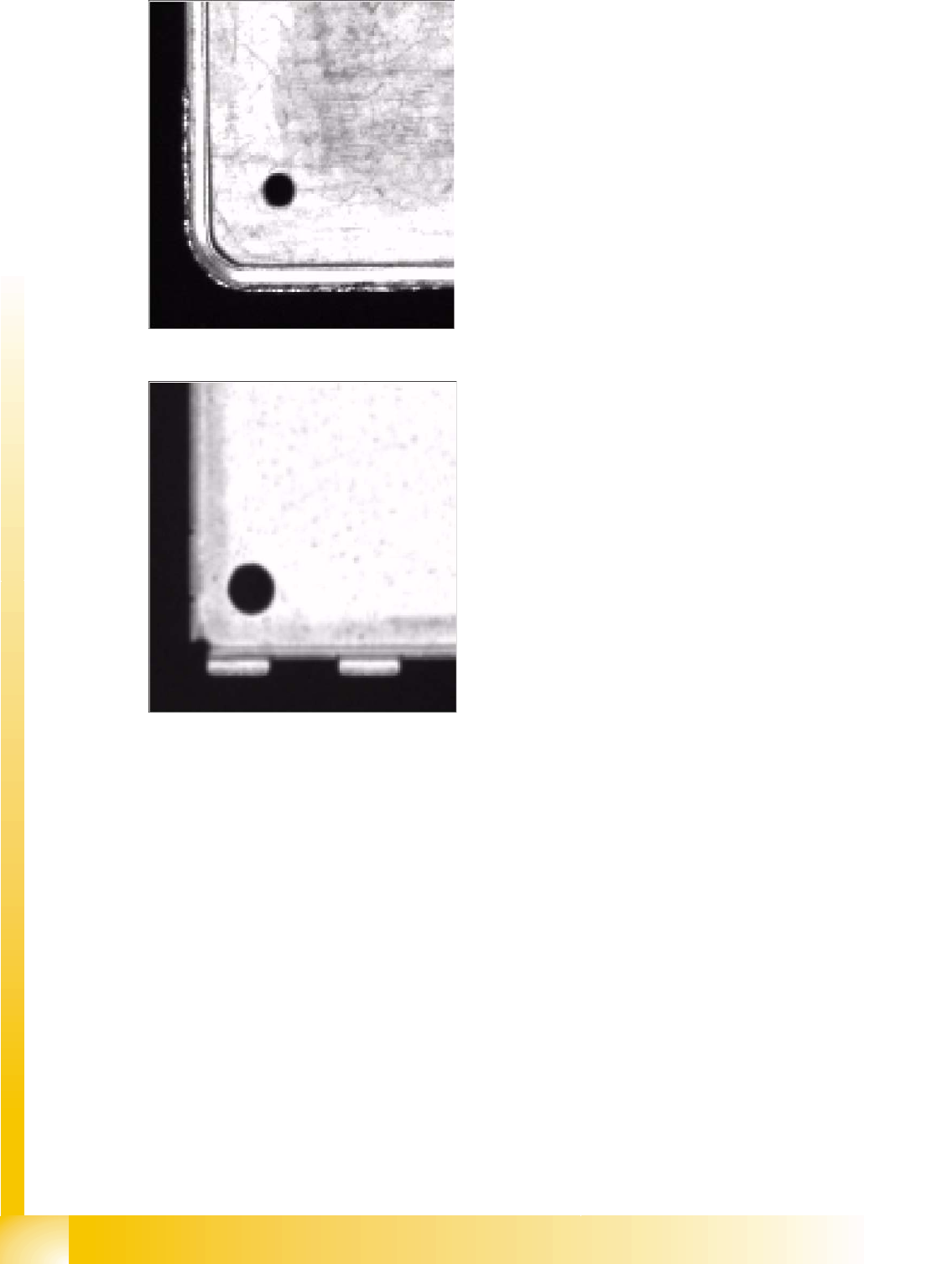
Filter type 251, for double edges caused by
springs or recesses;
Binary diagram: automatically determines a
suitable gray value threshold for binarization of
the image. A binarized image only has two
gray values: 0 and 255. Edge recognition in the
binary image is performed with an additional
scan (for Shields with springs and double
edges caused by shield indentations and
steep illumination. The bottom part of the
shield in the diagram has protruding elements,
which the measuring result is not supposed to
determine, and a double edge). If this filter type
is needed for a corner, we advise you to set it
for all corners. This means that the position is
determined in the same manner for all corners,
increasing measurement accuracy.
Component Shapes
Optical Recognition of Shields Specific Component Shapes
Student Guide SIPLACE Vision (Customer)
Edition 12/2008 EN Component Shapes
95
5.3.12 Optical Recognition of Shields
The shield centering procedure determines the CO center position, based on corner recognition data.
A.) Coarse and
B.) Fine centering.
If no circles or similar are programmed, further component inspections will not be performed.
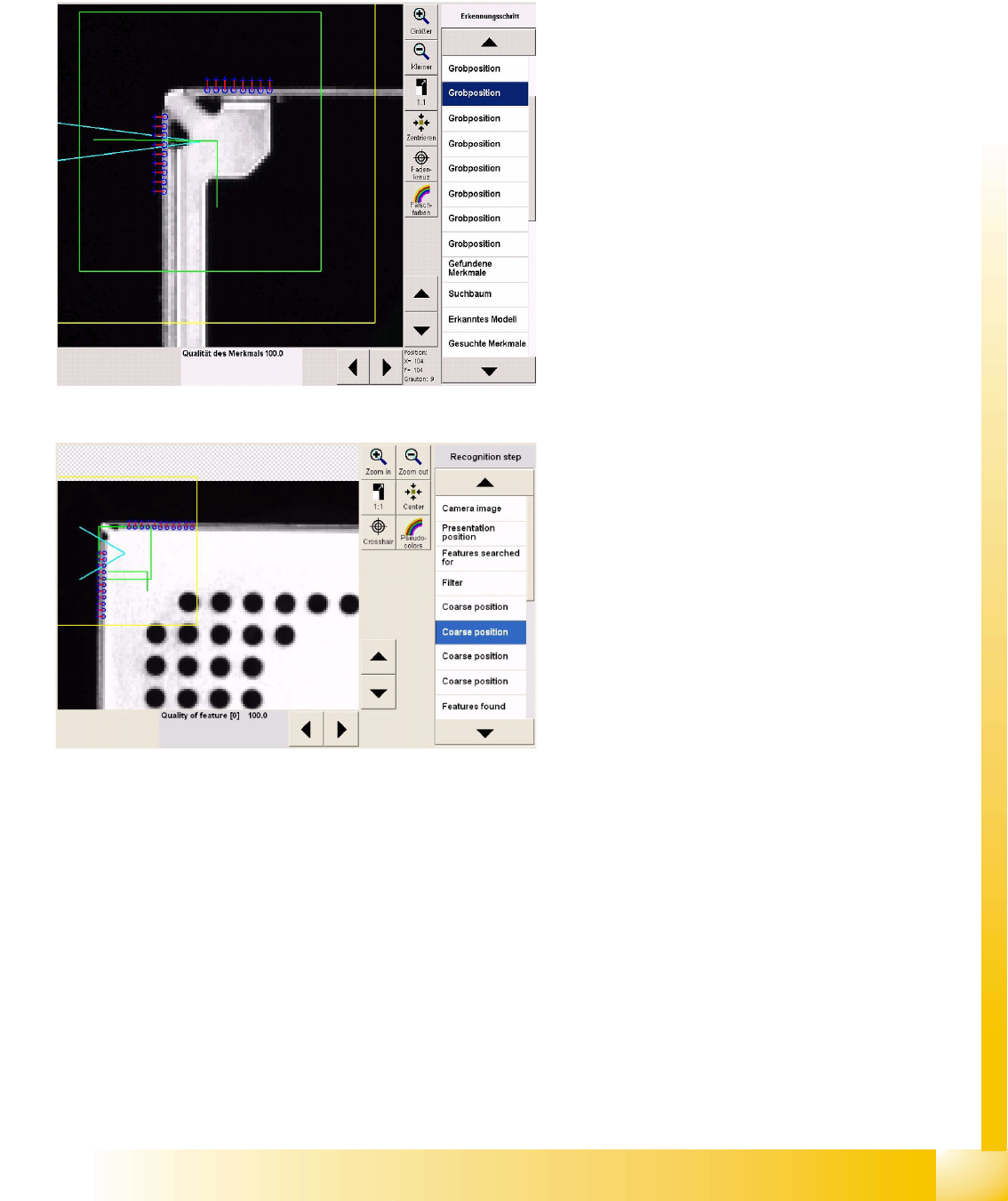
Coarse centering outer corner
As can be seen in the camera gray image, the
system searches for the brighter edge, from
outside.
Taken from below, these camera images usually
have a double edge at the outer corners. The
vertical sheet trim (arrow) forms the body height
and can be clearly recognized on both sides of the
corner, due to the corner recesses in the shield
cover.
On the horizontal side of the corner, the double
edge only covers 1.4 mm.
The defined image pairs are used to determine the
dark background (blue cross) and the
lighter CO body (blue ring).
Coarse centering inner corner
This double inner corner with corner protrusion
and slant will not be programmed, as the leg
lengths are too short. We recommend that you
create the distance between corners 2 mm greater
than the corner protrusion.
The vertical recognition line is set to the shortest
possible length of 1.8 mm (six image pairs with
minimum pitch).