00195044-14_UM_VisionTeachStation_DE EN.pdf - 第120页
5 Installing the cameras Vision Teach Station User Manual 5.1 Installing stationary cameras, type 25, 33 and 36 05/2015 Edition 120 5 Fig. 5.1 - 2 Connecting cable set 03040355-xx (1) DIP switches for camera type and loc…
Vision Teach Station User Manual 5 Installing the cameras
05/2015 Edition 5.1 Installing stationary cameras, type 25, 33 and 36
119
5.1.1 Connecting cable set 03040355-xx to the camera
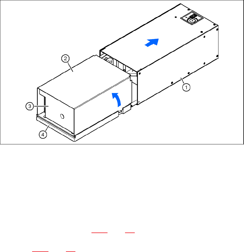
5.1.1.1 Opening the camera
Place the camera with the base plate (item 4) on a flat, clean surface.
Pull the illumination head (item 1) forward 30 mm or so.
Lift and remove the cover (item 2) from the base module (item 3).
The plug-in connectors and DIP switches are now accessible.
5
Fig. 5.1 - 1 Opening camera type 33
(1) Illumination head
(2) Cover
(3) Base module
(4) Base plate
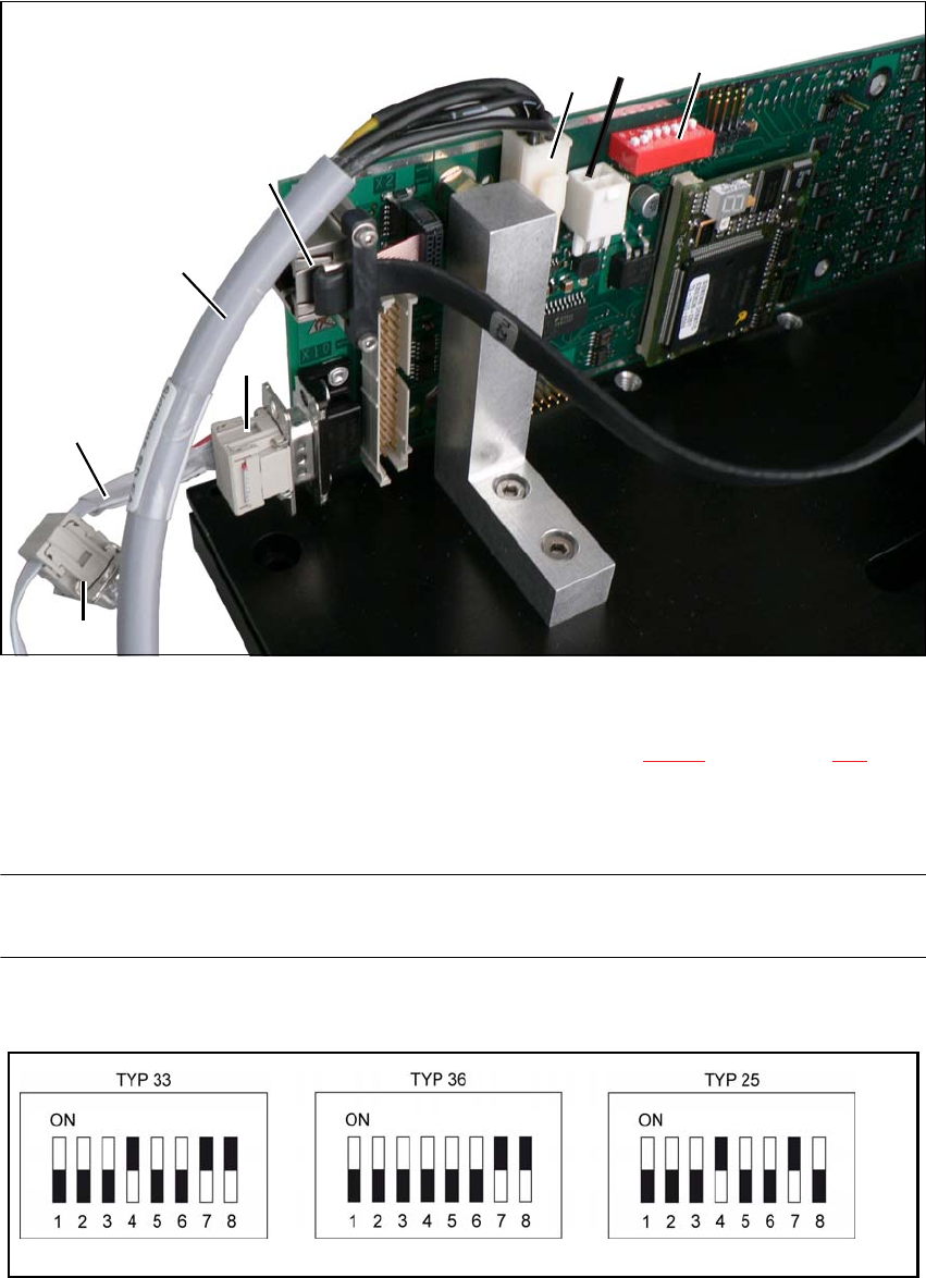
5.1.1.2 Connecting the cables and checking the DIP switches
Connect connector X4 on the cable 03040355-W1 to connector X4 on the board. This supplies
the camera with power (see Fig. 5.1 - 2, page 120).
Connect connector X10 on the cable 03040355-W2 to connector X10 on the board (CAN bus)
(see Fig. 5.1 - 2, page 120).
5 Installing the cameras Vision Teach Station User Manual
5.1 Installing stationary cameras, type 25, 33 and 36 05/2015 Edition
120
5
Fig. 5.1 - 2 Connecting cable set 03040355-xx
(1) DIP switches for camera type and location address
(2) Camera connector for camera cable direct to the PC (see Fig. 4.3 - 2, no. 1, page 117)
X4, X5 power supply connection, connected in parallel
X10 CAN bus connection
NOTE 5
Fit the camera to the base module before you connect the camera bus cable.
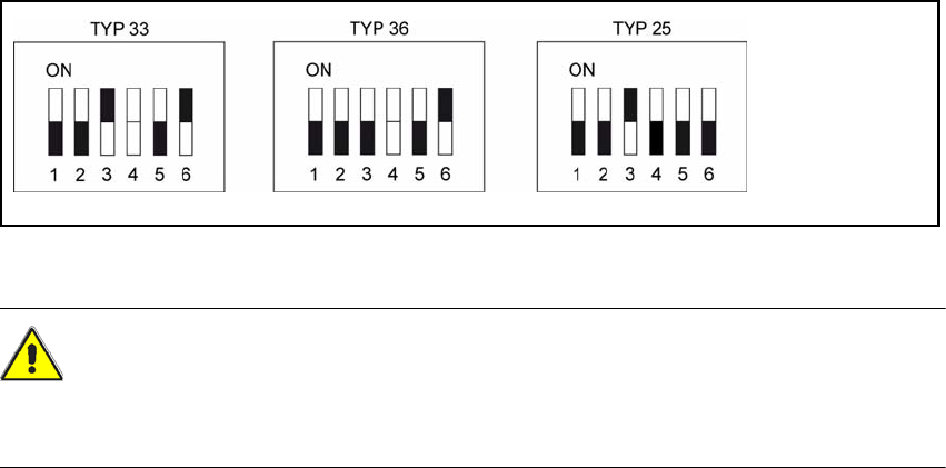
Check the DIP switch settings on the cameras.
Fig. 5.1 - 3 DIP switch settings on the stationary cameras for the vision teach station (version with 8 switches)
03040355-W2
X12
03040355-W1
(1)
(2)
X4
X10
X5
Vision Teach Station User Manual 5 Installing the cameras
05/2015 Edition 5.1 Installing stationary cameras, type 25, 33 and 36
121
Fig. 5.1 - 4 DIP switch settings on the stationary cameras (version with 6 switches)
CAUTION 5
In the version with 6 switches, switch no. 4 must NOT be changed, as this might cause malfunc-
tion of the LED self test.
5