00196613-0102_AI_LP-Dicke6mmDE+EN.pdf - 第14页
1 Montageanleitung LP-Dicke 6 mm SIPLACE SX1 / SX2 LP-Dicke 6 mm Ausgabe 06/2009 14 : Montieren Sie alle Klemmleisten und S topper . 1 Drücken Sie beim Festschra uben die T ransportwangen nach außen (an die Anlagekante).…
LP-Dicke 6 mm 1 Montageanleitung LP-Dicke 6 mm SIPLACE SX1 / SX2
Ausgabe 06/2009
13
: Achten Sie darauf dass die Leisten zur Außenseite der Transportwange ausgerichtet werden.
Legen Sie dazu die Klemmleiste so dass die LP-Klemmkante nach oben zeigt.
1
1
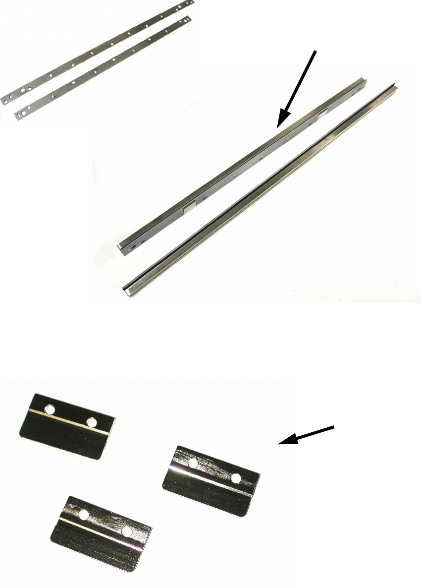
: Demontieren Sie alle Stopper und legen Sie die Distanzleiste 29 mm unter.
Setzen Sie die Plättchen unter jeden Stopper (je 3 an jeder Transportwange).
1
Leisten zum Unterlegen
Klemmleisten mit untergelegten Leisten
Plättchen

1 Montageanleitung LP-Dicke 6 mm SIPLACE SX1 / SX2 LP-Dicke 6 mm
Ausgabe 06/2009
14
: Montieren Sie alle Klemmleisten und Stopper.
1
Drücken Sie beim Festschrauben die Transportwangen nach außen (an die Anlagekante). 1
1
1
: Messen Sie erneut die Höhe des Transportes an mindestens 4 Stellen wie im Bild auf Seite 9
dargestellt. Diese muss wieder 176,8 +/-0,2 mm betragen.
1
Die Höhe muss genau eingehalten werden, sonst besteht Crash-Gefahr. 1
1
1
: Sofern noch nicht geschehen, sollten Sie nun den Optionalen Stopper montieren. Lesen Sie
hierzu die Montageanleitung Optionaler Stopper SIPLACE SX1/SX2 (Art.Nr.: 00196449-xx).
1
1
6 mm PCB thickness 2 Assembly instructions: 6 mm PCB thickness SIPLACE SX1 / SX2
06/2009 Edition
15
2 Assembly instructions:
6 mm PCB thickness
SIPLACE SX1 / SX2
2.1 General
The installation kit is designed for a single conveyor lane.
If you have a dual conveyor, you will have to order this option twice. 2
The installation kit contains optional stoppers. You will need these because printed circuit boards
that are between 0.5 mm and 2.5 mm thick can no longer be stopped reliably with the standard
stopper. You will find more details about installing the optional stoppers in the 00196449 Assembly
Instructions: Optional Stopper. 2
It will take approximately 30 minutes to fit the additional spacers. You will find the time needed to
fit the additional stoppers in the associated instructions. 2
2.2 Restrictions
If the PCB were stopped with the standard stopper, then the minimum thickness of 2.5 mm would
be correct. 2
If the PCB is stopped with the optional stopper, there is no restriction in terms of the minimum
thickness. 2
After conversion, the standard stopper can only stop PCB thicknesses of 2.5 mm to 6 mm. 2
The optional stopper can be used to stop PCBs that are from 0.5 to 6 mm thick. 2
2
2
2