00190935-01.pdf - 第32页
Pipettenwechsler Siplace 80S15/F3/S20/F4 Nozzle Changer Nachrüstanleitung/Retrofitting Instructions Ausgabe/Edition 03/97 Seite/Page 32 von/of 44 Figure 4: Fitting the nozzle changer • Insert the alignment pins into the …
Nachrüstanleitung/Retrofitting Instructions Pipettenwechsler Siplace 80S15/F3/S20/F4 Nozzle Changer
Ausgabe/Edition 03/97
Seite/Page 31 von/of 44
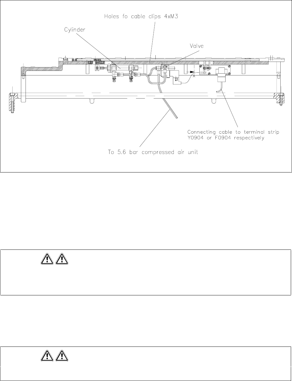
Figure 3 Connections on the revolver head nozzle changer
• Remove the feeders from the components table on the relevant side of the machine and move the
components table out of the machine.
• On machines 1 to 50, remove the right-hand buffer for the components table (see figure 2).
• Remove the used tape guide channel.
Please note
Machines 1 to 50 have a metal rail (support for the used tape guide channel) in place of the cast iron
rail.
• Remove the cast iron or metal rail (see figure 2).
• Fit the tape guide channel and, on all the machines, place the edge protector on the edge of the tape
guide channel in order to prevent damage to the connecting cable (see figure 2).
Please note
The support holder is already fitted in machines supplied after week 16/95.
• Attach the compressed air supply to the valve on the nozzle changer.
• Attach connecting cable Y0553-W2 or Y0553-W1 to the nozzle changer control board (see figure 3).
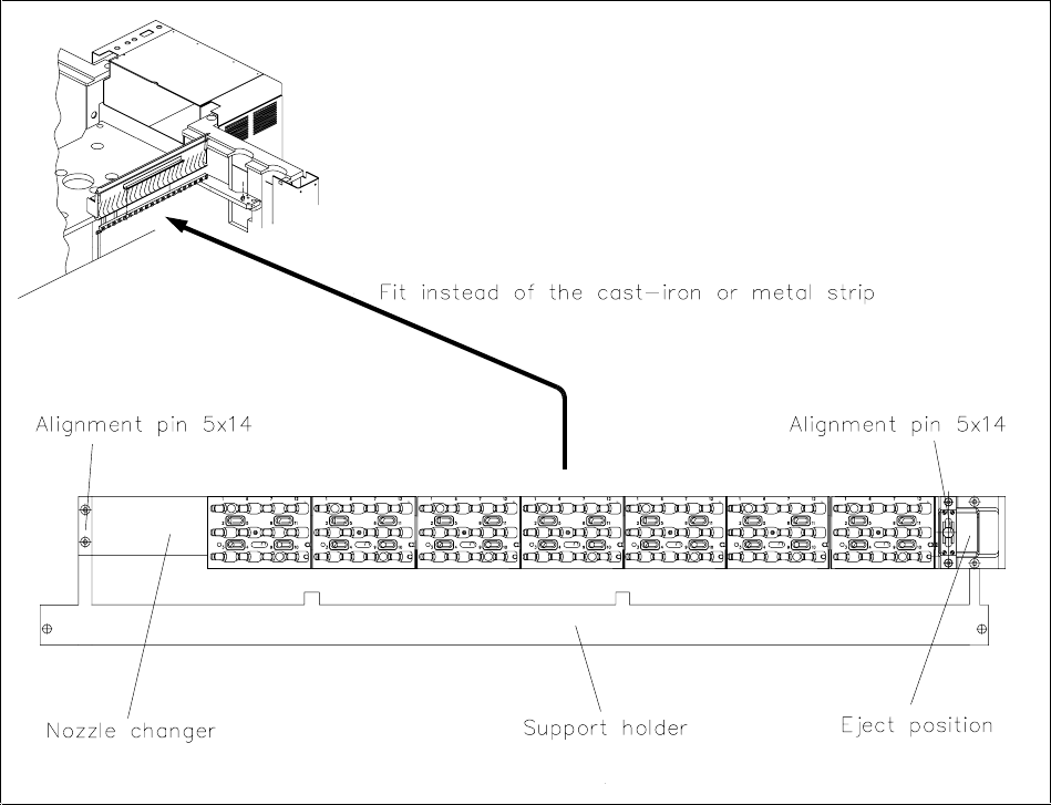
Pipettenwechsler Siplace 80S15/F3/S20/F4 Nozzle Changer Nachrüstanleitung/Retrofitting Instructions
Ausgabe/Edition 03/97
Seite/Page 32 von/of 44
Figure 4: Fitting the nozzle changer
• Insert the alignment pins into the support holder (see figure 4).
• Using the cable clips, fix the connecting cable and the compressed air hose to the nozzle changer at
the holes provided.
• On machines 1 to 50, fix the cast iron or metal rail to the used tape guide channel.
• Screw the nozzle changer onto the support holder (see figure 4).
Nachrüstanleitung/Retrofitting Instructions Pipettenwechsler Siplace 80S15/F3/S20/F4 Nozzle Changer
Ausgabe/Edition 03/97
Seite/Page 33 von/of 44
1.5.1.1 Laying the cables and compressed air hoses
Figure 5: Creating the connections
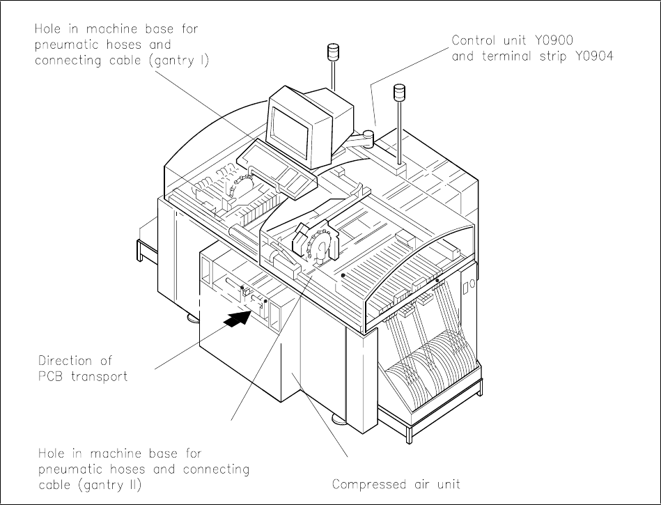
1.5.1.2 Gantry 1 (Siplace 80S15/F3)
• Dismantle the control unit.
• Push the connecting cable Y0553-W1 through the hole in the machine frame to terminal panel Y0904
(see figure 5).
• Push the compressed air hose through the hole in the machine frame and into the machine.
• Using a suitable tool (e.g. a rod), pull the compressed air hose through the inside of the machine to the
compressed air unit.
• Tie the cable and compressed air hose together with cable lacing.