00190935-01.pdf - 第33页
Nachrüstanleitung/Retrofitting Instructions Pipettenwechsler Siplace 80S15/F3/S20/F4 Nozzle Changer Ausgabe/Edition 03/97 Seite/Page 33 von/of 44 1.5.1.1 Laying the cables and compressed air hoses Figure 5: Creating the …
Pipettenwechsler Siplace 80S15/F3/S20/F4 Nozzle Changer Nachrüstanleitung/Retrofitting Instructions
Ausgabe/Edition 03/97
Seite/Page 32 von/of 44
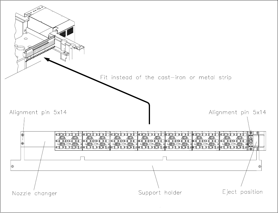
Figure 4: Fitting the nozzle changer
• Insert the alignment pins into the support holder (see figure 4).
• Using the cable clips, fix the connecting cable and the compressed air hose to the nozzle changer at
the holes provided.
• On machines 1 to 50, fix the cast iron or metal rail to the used tape guide channel.
• Screw the nozzle changer onto the support holder (see figure 4).
Nachrüstanleitung/Retrofitting Instructions Pipettenwechsler Siplace 80S15/F3/S20/F4 Nozzle Changer
Ausgabe/Edition 03/97
Seite/Page 33 von/of 44
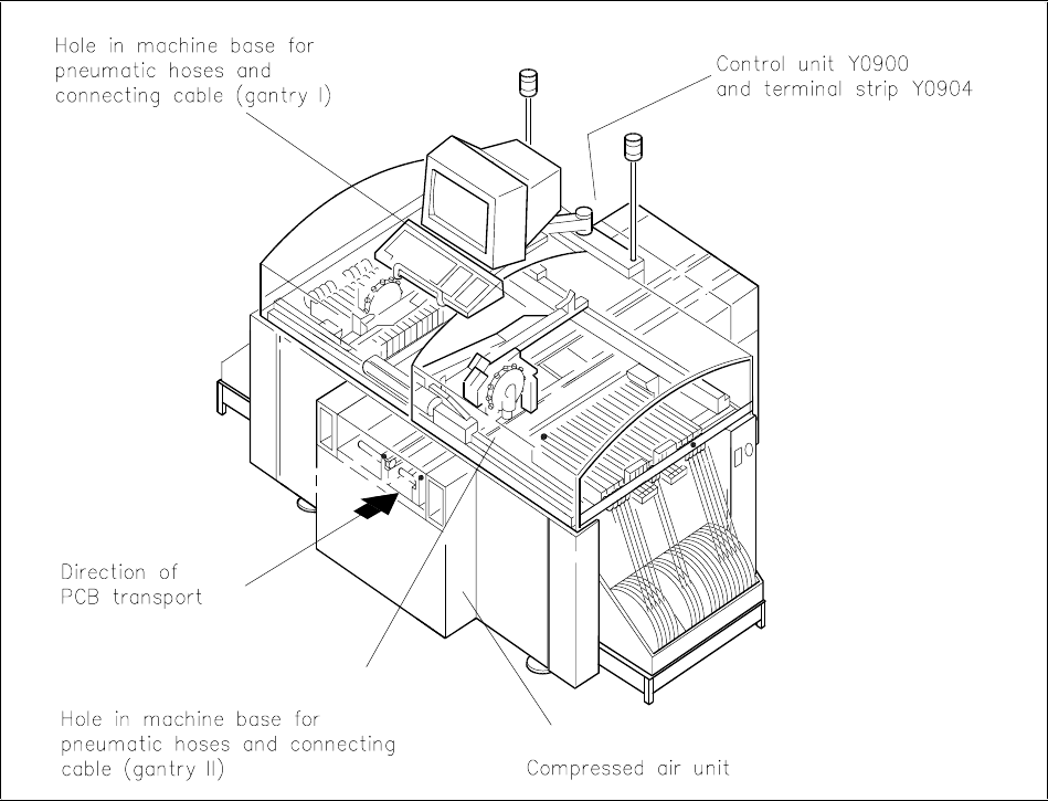
1.5.1.1 Laying the cables and compressed air hoses
Figure 5: Creating the connections
1.5.1.2 Gantry 1 (Siplace 80S15/F3)
• Dismantle the control unit.
• Push the connecting cable Y0553-W1 through the hole in the machine frame to terminal panel Y0904
(see figure 5).
• Push the compressed air hose through the hole in the machine frame and into the machine.
• Using a suitable tool (e.g. a rod), pull the compressed air hose through the inside of the machine to the
compressed air unit.
• Tie the cable and compressed air hose together with cable lacing.
Pipettenwechsler Siplace 80S15/F3/S20/F4 Nozzle Changer Nachrüstanleitung/Retrofitting Instructions
Ausgabe/Edition 03/97
Seite/Page 34 von/of 44
1.5.1.3 Gantry 2 (Siplace 80S15)
• Dismantle the control unit.
• Push connecting cable Y0553-W2 through the hole in the machine frame to the compressed air unit
(see figure 5).
• Using a suitable tool (e.g. a rod), pull the connecting cable Y0553-W2 from the compressed air unit,
through the machine frame to the terminal panel Y0904.
• Push the compressed air hose through the hole in the machine frame to the compressed air unit.
• Tie the cable and compressed air hose together with cable lacing.
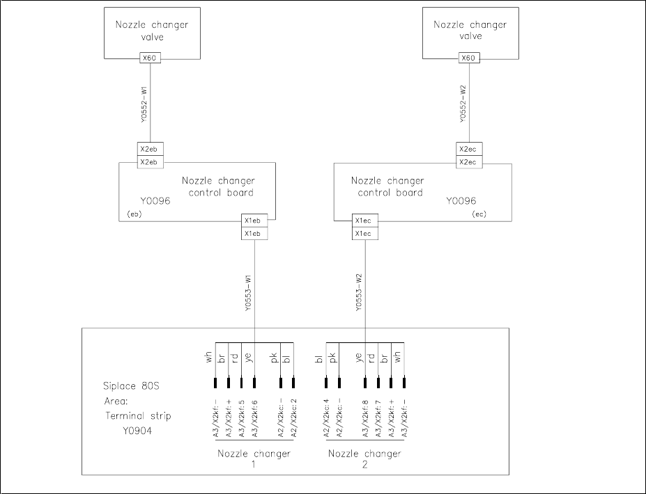
1.5.1.4 Electrical connections
• Guide the connecting cable Y0553-W1 or Y0553-W2 through the cable duct into the terminal panel
Y0904.
• Connect terminal Y0553-W1 or Y0553-W2 on the nozzle changer to the terminal panel Y0904 as
shown in the following terminal diagrams (figures 6 and 7).
• Please note that there are differences between the Siplace 80S15 and 80F3.
Figure 6: Connecting the power cable of the revolver head nozzle changer to the Siplace 80S15