88192277-01-18 - Micron Technical Reference V9 Volume 1.pdf - 第40页
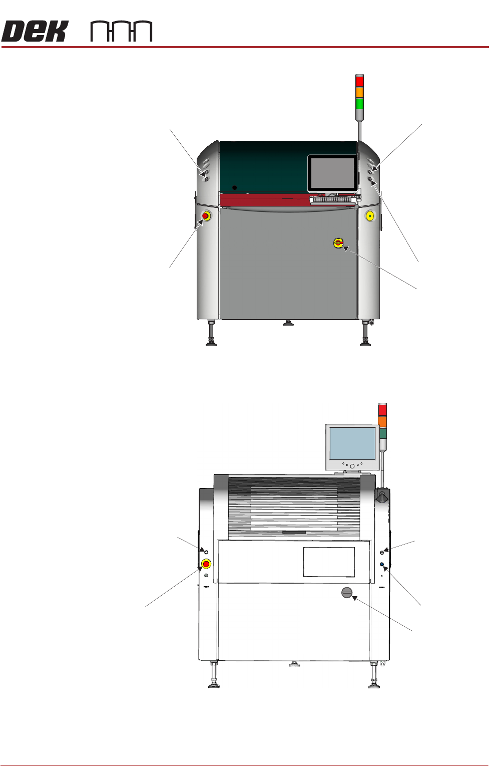
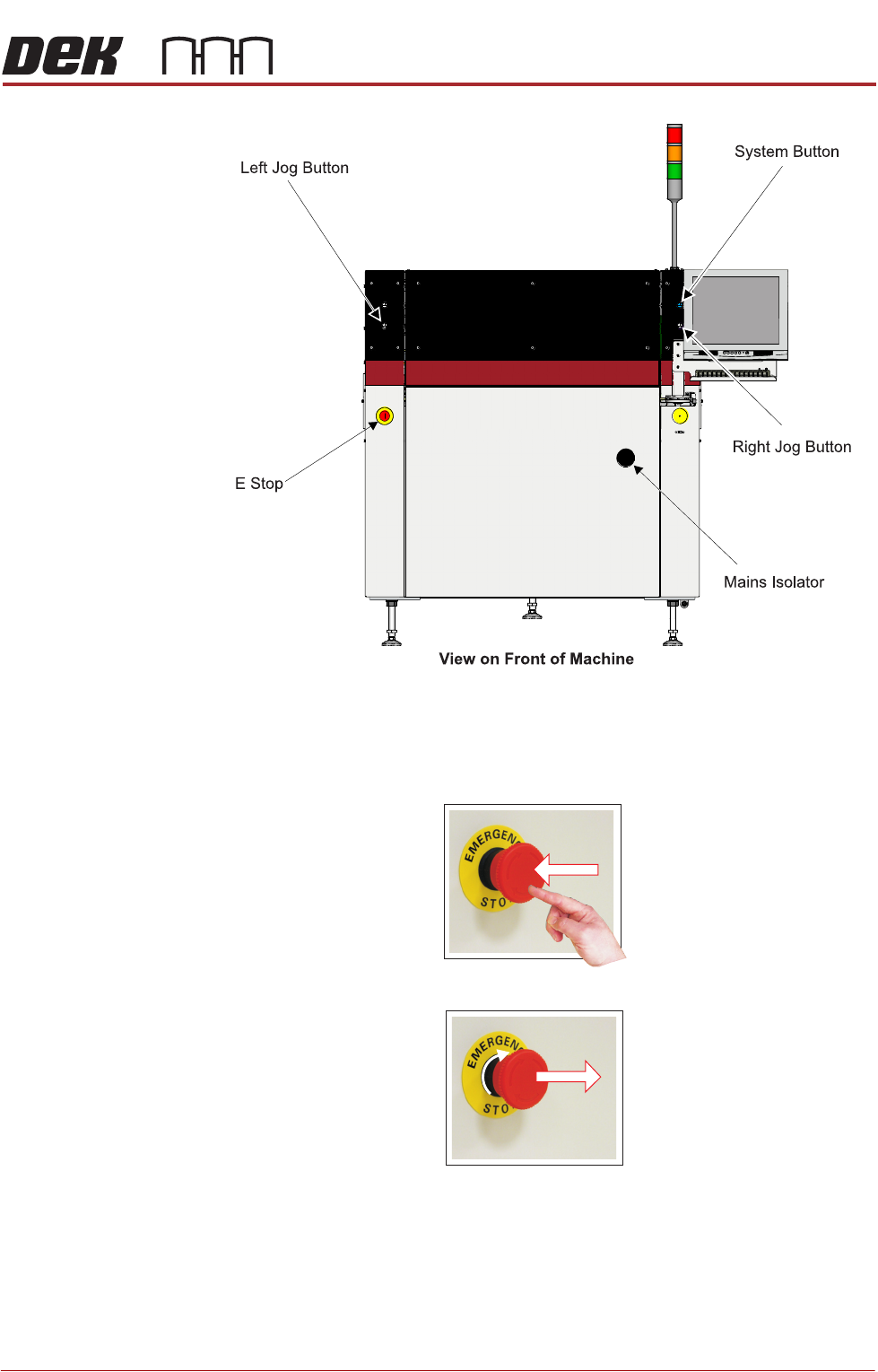
SAFETY FEATURES GENERAL 2.12 Technical Reference Manual Chapter Issue 16, Nov 19 Figure 2-4 T ype 4 View on Front of Machine Left Jog Button E Stop System Button Mains Isolator
SAFETY FEATURES
GENERAL
Chapter Issue 16, Nov 19 Technical Reference Manual 2.11
Figure 2-2 Type 2
Figure 2-3 Type 3
View on Front of Machine
Right Jog Button
System Button
Mains Isolator
Left Jog Button
E Stop
Left Jog Button
Right Jog Button
System Button
View on Front of Machine
E Stop
Mains Isolator
SAFETY FEATURES
GENERAL
2.12 Technical Reference Manual Chapter Issue 16, Nov 19
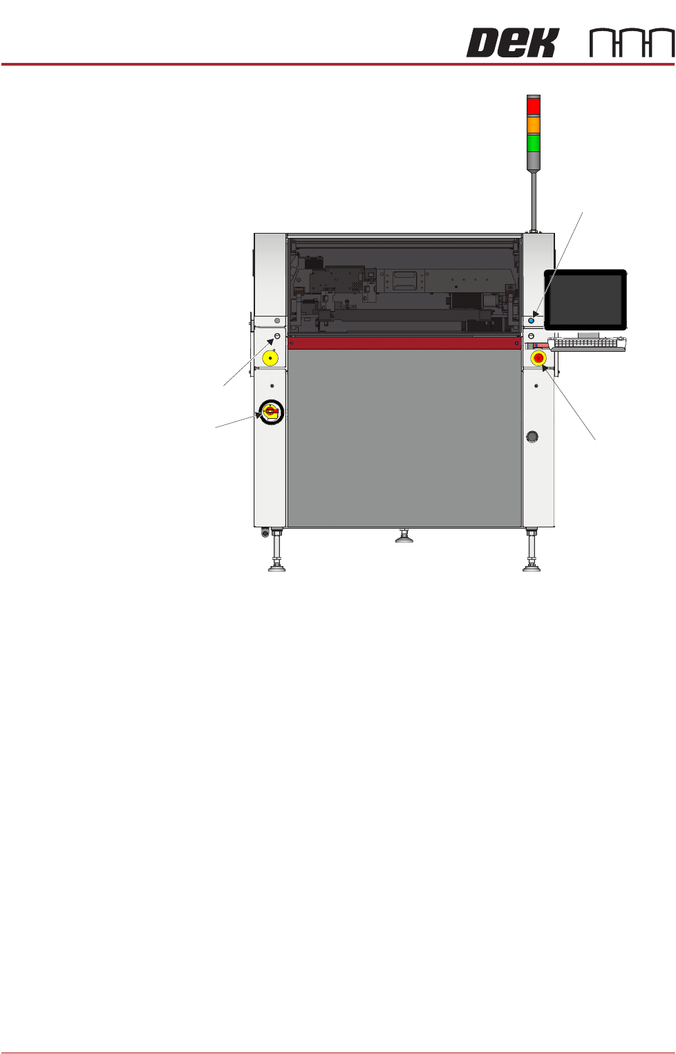
Figure 2-4 Type 4
View on Front of Machine
Left Jog Button
E Stop
System Button
Mains
Isolator
SAFETY FEATURES
GENERAL
Chapter Issue 16, Nov 19 Technical Reference Manual 2.13
Figure 2-5 Type 5
Emergency Stop (E
Stop)
The machine is fitted with an E Stop which suspends all machine operations.
The switch is within easy reach of the operator and once pressed, the latching
switch requires resetting.
To reset the E Stop, turn the button clockwise until it unlatches.
Pressing the E Stop or opening the printhead cover cuts the servo axes power
supply. A warning of this condition is reported on the machine monitor.