M6ex_ServiceManual_e.pdf - 第84页
4 Electrical Section 4-18 ■ Device 12 Address Bit No. Signal Name Address Bit No. Signal Name 0000h 0 Device No. Bit0 0002h 0 MXR E-axis ORG / MX20 Z-axis ORG 1 Device No. Bit1 1 MXR E- axis OR+ / MX Z-axis OR+ 2 Device …
4 Electrical Section
4-17
Address
Bit
No.
Signal Name Address
Bit
No.
Signal Name
0004h 0 Y-axis ORG 0008h 0 Rear Clamp On
1 Y-axis OP- 1 Rear Clamp Off
2 Y-axis OR+ 2 Side Clamp On
3 3 Side Clamp Off
4 X-axis ORG 4
5 X-axis OR- 5
6 X-axis OR+ 6
7 7 Conveyor Width Sensor
0005h 0 0009h 0
1 1
2 2
3 3
4 Air Pressure Down (failure) 4 AWC OR+
5 Ready Input 5 Grid-Lok On
6 Board Available Input 6
7 AWC Pin Detection 7
0006h 0 CFB(F) Lock 000Ah 0
1 CFB(F) Unlock 1
2 CFB(F) Check 1 2
3 3
4 CFB(R) Lock 4
5 CFB(R) Unlock 5
6 CFB(R) Check 1 6
7 7
0007h 0 ANC A Close 000Bh 0 Conveyor1 Alarm
1 ANC A Open 1 Conveyor2 Alarm
2 ANC B Close 2 Conveyor3 Alarm
3 ANC B Open 3
4 4
5 5
6 MXST2 L Position 1 6
7 MXST2 L Position 2 7
4 Electrical Section
4-18
■ Device 12
Address
Bit
No.
Signal Name Address
Bit
No.
Signal Name
0000h 0 Device No. Bit0 0002h 0 MXR E-axis ORG / MX20 Z-axis ORG
1 Device No. Bit1 1 MXR E-axis OR+ / MX Z-axis OR+
2 Device No. Bit2 2 MXR Pallet I/L
3 Device Added Information Bit0 3 MXR H1-axis ORG / MX20 Y1-axis ORG
4 Device Added Information Bit1 4 MXR Pallet Bar Close2
5 Device Added Information Bit2 5 MXR Stocker I/L / MX20 Stocker I/L
6 Device Added Information Bit3 6 MXR Hook Lock / MX20 Relay Hook Retract End
7 Output Register Value Bit0 7
MXR Pallet Detect on Hook /
MX20 Pallet Detect on Shuttle
0001h 0 Output Register Value Bit1 0003h 0
MXR Pallet Bar Open1 /
MX20 Pallet Interlock in Stocker
1 Output Register Value Bit2 1
MXR Pallet Bar Open2 /
MX20 Pallet Stopper Off in Stocker
2 Output Register Value Bit3 2
MXR Pallet Bar Close1 /
MX20 Pallet Clamp Off on Shuttle
3 Output Register Value Bit4 3
MXR Pallet Detect in Stocker /
MX20 Pallet Detect in stocker
4 Input Register Value Bit0 4 MXR Hook Unlock / MX20 Relay Hook Down
5 Input Register Value Bit1 5 W-MXR SETUP Switch
6 Input Register Value Bit2 6 MXR Cover Open / MX20 Cover Open
7 Input Register Value Bit3 7 WMXR RELAY ON
4 Electrical Section
4-19
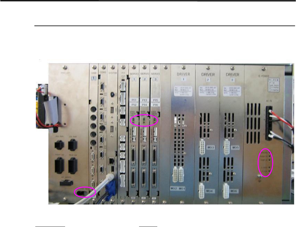
System Box Assembly
Various control boards are built in the system box assembly. Refer to their features and points to be
checked.
Board name
Feature
D.POWER: Supplies power source to the motor drive boards.
DRIVER: Transmits outputs from the servo board to each motor.
SERVO: Controls AC servo motors that run each axis of the mounter.
IFC2: Controls feeders, the signal tower, illuminations, etc.
SYSTEM: Controls each control board and the mounter system.
CDA2: Controls the whole serial I/O.
VM8: Transfers images taken by the cameras to the mounter system.