M6ex_ServiceManual_e.pdf - 第86页
4 Electrical Section 4-20 LED conditions Board name LED C olor LED in operati ng status D.POWER CHARGING Yello w Lights when the power is charged properly . PHASE OK Green Lights when the power source is good. TEMP OK Gr…
4 Electrical Section
4-19
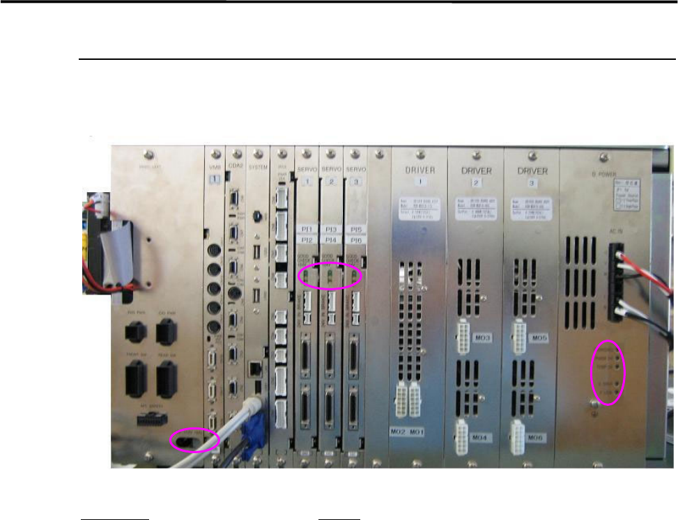
System Box Assembly
Various control boards are built in the system box assembly. Refer to their features and points to be
checked.
Board name
Feature
D.POWER: Supplies power source to the motor drive boards.
DRIVER: Transmits outputs from the servo board to each motor.
SERVO: Controls AC servo motors that run each axis of the mounter.
IFC2: Controls feeders, the signal tower, illuminations, etc.
SYSTEM: Controls each control board and the mounter system.
CDA2: Controls the whole serial I/O.
VM8: Transfers images taken by the cameras to the mounter system.
4 Electrical Section
4-20
LED conditions
Board name
LED Color LED in operating status
D.POWER
CHARGING
Yello
w
Lights when the power is charged properly.
PHASE OK Green Lights when the power source is good.
TEMP OK Green
Lights when the temperature is normal.
(65 degrees Celsius or higher)
V.OVER Red Lights when motor control voltage is high.
V.LOW Red Lights when motor control voltage is low.
SERVO
GOOD Green Lights when the servo board is in good condition.
CHECK
Yello
w
Lights when the servo’s firmware works properly.
+24V
Yello
w
Lights when the power source of the mechanical brake is on.
IFC2
LED1 Green Lights when data is written properly.
LED2 Green Lights when the system works properly.
CDA2
COM0 Green Lights when the CN1 exchanges serial data properly.
COM1 Green Lights when the CN2 exchanges serial data properly.
COM2 Green Lights when the CN3 exchanges serial data properly.
COM3 Green Lights when the CN4 exchanges serial data properly.
COM4 Green Lights when the CN5 receives serial data properly.
COM5 Green Lights when the CN6 exchanges serial data properly.
COM6 Green Lights when the CN5 receives serial data properly.
COM7 Green Lights when the CN8 exchanges serial data properly.
PWR Green Lights when the mounter system works properly. (IC1)
PWR Green Lights when the mounter system works properly. (IC2)
VM8 LED1 Blue
Lights from the start of image capture to the end of data
transfer.
LED1 Red Lights when a fatal error such as hang-up occurs.
PWR Green Lights when the system works properly.
INT Red Lights when image processing process is interrupted.
PCI Green
Lights when exchanging data between the CPU and the
VM8.
CBP2 +5V Green
Lights when the power source +5V is in good condition.
( +4.5V to +5.6V)
+12V Green
Lights when the power source +12V is in good condition.
(+10.6V to +13.4V)
+24V Green
Lights when the power source +24V is in good condition.
(+21.5V to +26.7V)
These are visual check items when the mounter is turned on. To check the inside of the mounter,
be sure to turn off the mounter in advance.
Vacuum and dust the vent with a vacuum cleaner. (Do not use an air blower.)
4 Electrical Section
4-21
Control Board
Handling Control Board
Note the followings when handling PC boards.
Do not touch control boards by wet hands.
Do not handle control boards where there are metal chips around.
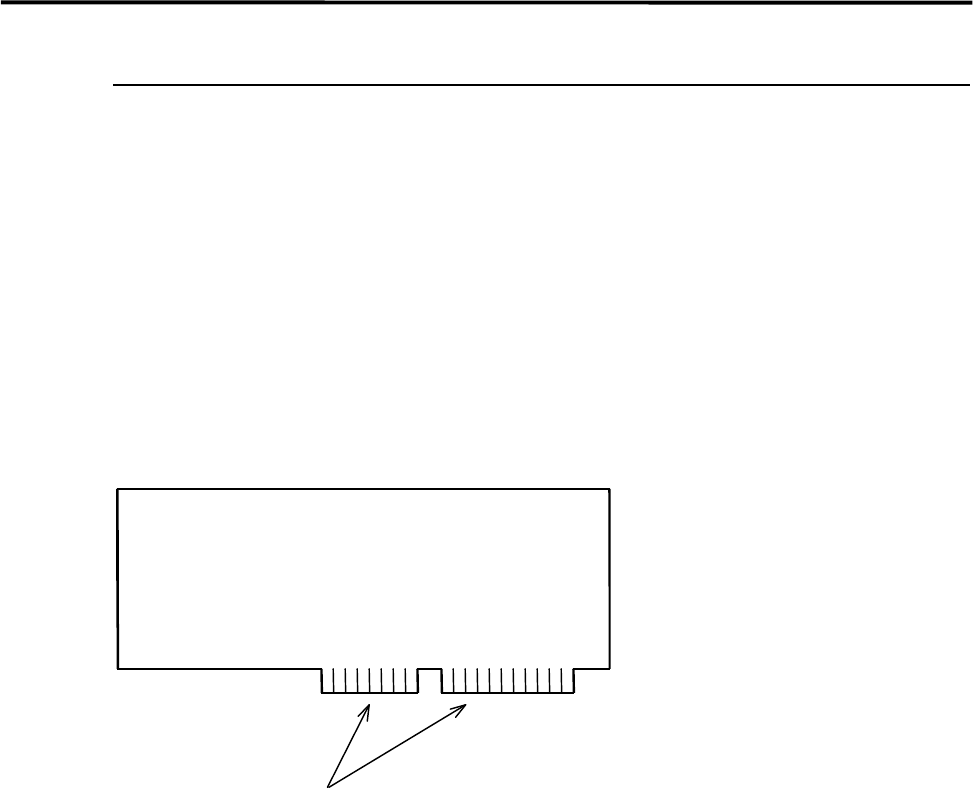
To handle control boards in the control rack, never touch the connecting portion where gold is plated. If
the connecting portion is covered with dust, the machine doesn't work properly. Clean with alcohol.
Gold Plating