3OM-1343-008_w.pdf - 第118页
3-33 AKFEDT -ID 1.3 Placement Head/Nozzle Data (B01_01) Head 1, 2, 3, and 4 Nozzle 1 through 12, ID Names This data is used to allocate the nozzles to the speci fi ed positions (Nozzle Allocation Nos.) on the heads. 0601-…

3-32
AKFEDT-ID
1.2.5 (A04) Setup Data
Note
Unless "Enable" is selected for a device to be set up, the machine does not
perform any setup operation on the device.
(A04_01)
Conveyor
"Enable" or "Disable" can be selected to determine whether the
conveyor width should be set up or not after a program change
operation.
Disable :
The conveyor width setup operation is not performed.
Enable :
The conveyor width setup operation is performed.
(A04_02)
PCB Y Position Arrangement
It can be determined whether or not the PCB transfer section should
be moved in the optimum Y direction according to the pattern program
when a program change operation is performed.
Mode
Select either "Enable" or "Disable" in the "Mode" text box of the label
"PCB Y Position Arrangement".
Disable :
The Y position of the PCB is not arranged.
Enable :
The Y position of the PCB is arranged.
Specify Method
When "Enable" is set in the "Mode" text box, select one of the
following options.
Specifi ed Position :
The conveyor Y position in the PCB
positioning section is moved to the
specifi ed position.
Base Conveyor Fixation :
The PCB positioning section is fi xed to
the reference position.
Position [mm]
When "Specifi ed Position" is set in the "Specify Method" text box,
specify the distance of the PCB Y position (center) to be shifted from
the machine’s positioning center.
0604-003
1.2 Operation Data

3-33
AKFEDT-ID
1.3 Placement Head/Nozzle Data
(B01_01)
Head 1, 2, 3, and 4
Nozzle 1 through 12, ID Names
This data is used to allocate the nozzles to the specifi ed positions (Nozzle
Allocation Nos.) on the heads.
0601-002
1.3 Placement Head/Nozzle Data
3-34
AKFEDT-ID
1.4 Placement Feeder Location Data
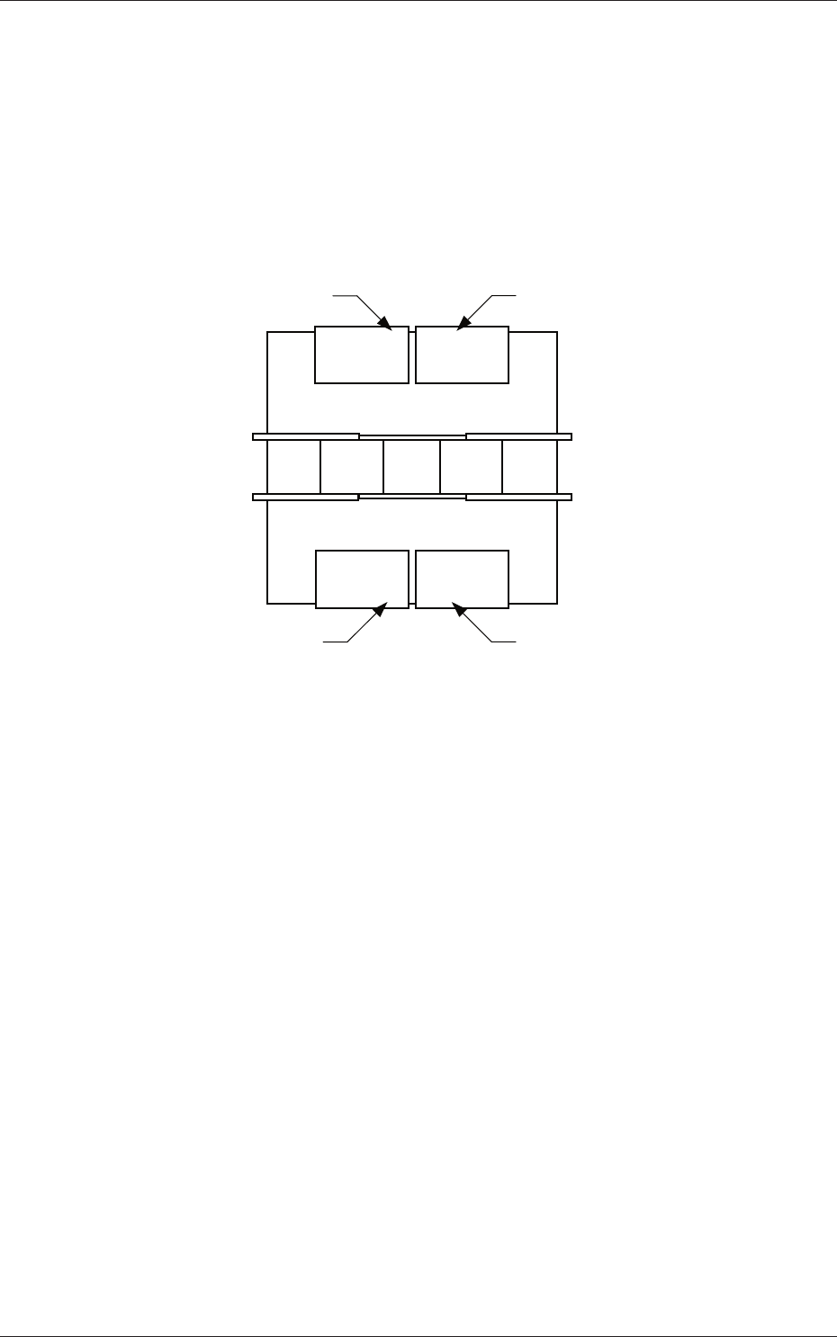
(C01) Feeder Bases #1, #2, #3, #4, and Work Area
It can be determined which components must be used and which feeder
base (Fdr No.) must be loaded with the selected components.
The tape feeders can be installed on the feeder bases.
Front Side of Machine
Rear Side of Machine
Feeder Base #1
Feeder Base #2
Feeder Base #3
Feeder Base #4
Fig. 3C26 Positional Relation between Feeder Bases
Work Area
The work area is the place where the data is stored temporarily.
This area is something like a virtual feeder base in which the data can
be stored temporarily and can be used to temporarily keep the data
overfl owing after data conversion, pattern program creation, etc.
0601-002
1.4 Placement Feeder Location Data