3OM-1343-008_w.pdf - 第144页
3-59 AKFEDT -ID 0601-002 2.4.2 Allocation of Component IDs (1) Select the "Feeder Base #" tab where a component ID should be allocated. (2) Select the feeder No. (Fdr No.) where a component ID should be allocat…
3-58
AKFEDT-ID
[5] [Link ID Tree Display] Button
When pressed, this button displays the link and root IDs that are
arranged side by side in the hierarchical (tree) fi le system.
[6] [Placement] Button
When pressed, this sets the component selected from the list of
component IDs in the placement feeder location data.
[7] [Replace] Button
When pressed, this button replaces the placement feeder location data
with the component selected from the list of component IDs.
[8] [Close] Button
When pressed, this button closes the "Component ID List" window.
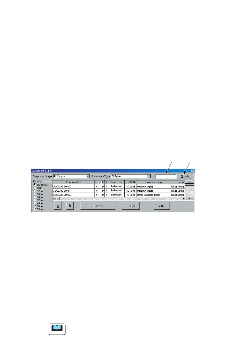
[9] [Search] Button
When pressed, this searches the required component ID.
(1) Enter the component ID to be searched, or using "*" (asterisk) and
"?" (question mark) as wild cards.
(1) (2)
Fig. 3C46
Example :
(a) When "AB*" is entered in the text box, all
component ID names starting with "AB" can be
searched.
(b) When "*CD" is entered, all component IDs
ending with "CD" can be searched.
(c) When "AB?DE" is entered, all component ID
names containing any character(s) between "AB"
and "DE" can be searched.
(2) Press the [Search] button.
Only the component IDs that meet the requirements are displayed.
Note
To clear the results of the search operation
(1) Make blank the text box beside the [Search] button.
(2) Press the [Search] button.
The original condition resumes.
0601-002
2.4 Allocation of Component IDs
3-59
AKFEDT-ID
0601-002
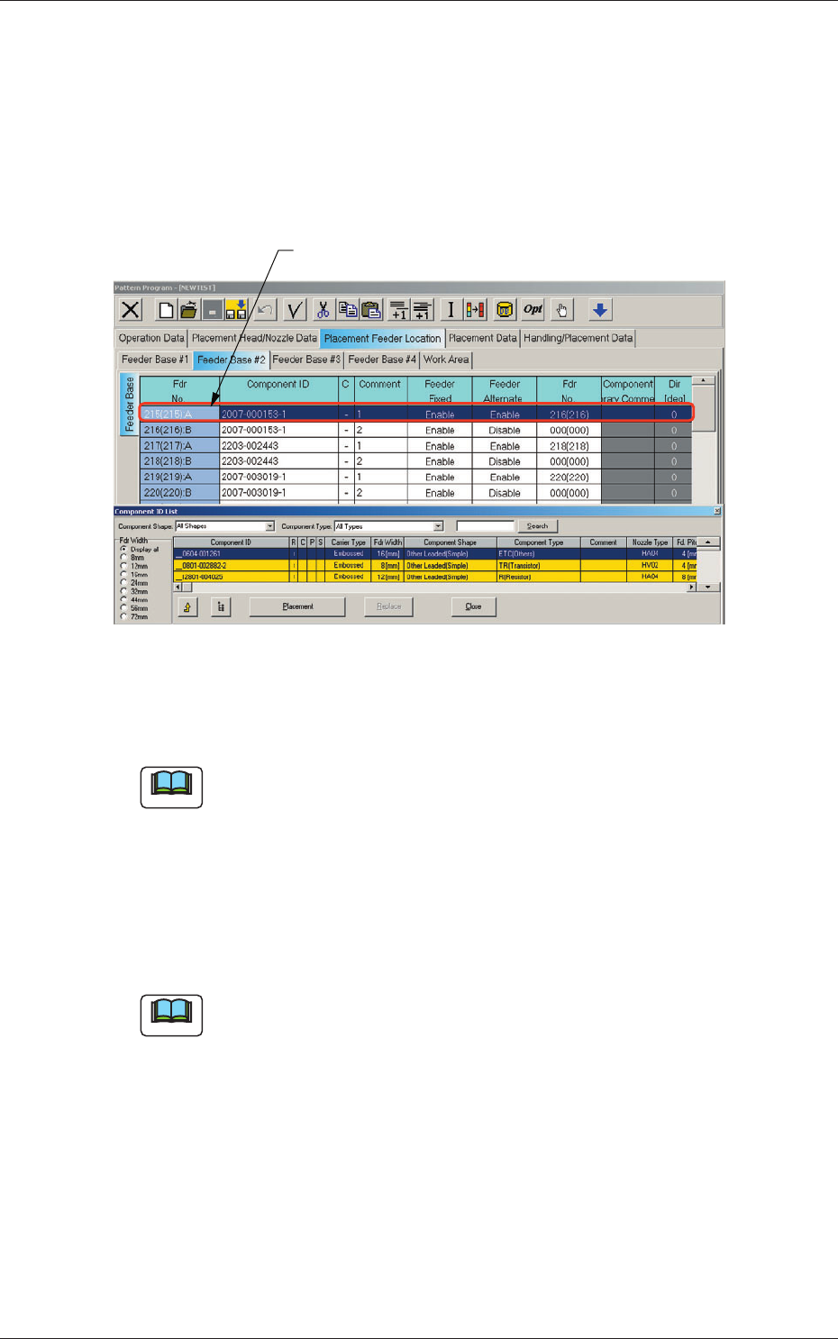
2.4.2 Allocation of Component IDs
(1) Select the "Feeder Base #" tab where a component ID should be
allocated.
(2) Select the feeder No. (Fdr No.) where a component ID should be
allocated.
The selected line (Fdr No.) turns blue, indicating that it is selected.
Selected Fdr No.
Fig. 3C47 Edit Window (Example)
(3) Select the desired component ID to be allocated in the "Component ID
List" window.
Note
When parameters are set in the "Component Shape" and "Component
Type" combo boxes and an option button in the "Fdr Width" group box is
selected, the component IDs based on the selections will be searched and
displayed quickly.
(4) Press the [Placement] button.
The selected component ID is allocated to the "Fdr No." line that has
turned blue.
Note
When the [Replace] button is pressed in place of the [Placement] button,
the component ID in the "Component ID" text box is replaced with the
component ID selected from the list of component IDs.
2.4 Allocation of Component IDs
3-60
AKFEDT-ID
2.4.3 Deletion of Allocated Component ID
(1) Select the desired "Feeder Base #" tab and the feeder No. (Fdr No.) of
the component to be deleted.
The selected line (Fdr No.) turns blue, indicating that it is selected.
(2) Select the [Cut] icon on the toolbar. The selected feeder No. (Fdr No.)
is deleted and the subsequent feeder Nos. are shifted up.
2.4.4 Setting of Dual Feeder Mode
(1) Select the range of "Fdr Nos." to be specifi ed as dual feeders.
(2) When the right button of the track ball is pressed with the range being
selected, a menu opens.
(3) Select "Set Up Dual Feeder" from the menu.
": A" or ": B" is assigned to "Fdr No." of the lines in the selected range.
Note
(a) Clicking the icon ( ) on the extended toolbar with a range of
feeders being selected also makes it possible to set the feeders in the
dual feeder mode.
(b) When a component ID of "Feeder Width: 8 mm" is allocated, "Dual
Feeder" is automatically set and ": A" or ": B" is added to the feeder
No. (Fdr No.).
2.4.5 Cancellation of Dual Feeder Mode
(1) Select the lines (Fdr Nos.) to cancel the dual feeder mode.
(2) When the right button of the track ball is pressed with the range being
selected, a menu opens.
(3) Select "Release Dual Feeder" from the menu.
The selected lines (Fdr Nos.) are released from the dual feeder mode.
Note
(a) Clicking the icon ( ) on the extended toolbar with a range of
feeders being selected also makes it possible to release the feeders
from the dual feeder mode.
(b) It is impossible to cancel the setting of "Dual Feeder" for the feeder
No. (Fdr No.) where a component ID of "Feeder Width: 8 mm" is
allocated.
0601-002
2.4 Allocation of Component IDs