3OM-1343-008_w.pdf - 第146页
3-61 AKFEDT -ID 2.5 Optimization of Pattern Program The currently opened pattern program can be optimized. When the optimize icon ( ) is pressed in the "Pattern Program" edit window , the "Make Placement/H…
3-60
AKFEDT-ID
2.4.3 Deletion of Allocated Component ID
(1) Select the desired "Feeder Base #" tab and the feeder No. (Fdr No.) of
the component to be deleted.
The selected line (Fdr No.) turns blue, indicating that it is selected.
(2) Select the [Cut] icon on the toolbar. The selected feeder No. (Fdr No.)
is deleted and the subsequent feeder Nos. are shifted up.
2.4.4 Setting of Dual Feeder Mode
(1) Select the range of "Fdr Nos." to be specifi ed as dual feeders.
(2) When the right button of the track ball is pressed with the range being
selected, a menu opens.
(3) Select "Set Up Dual Feeder" from the menu.
": A" or ": B" is assigned to "Fdr No." of the lines in the selected range.
Note
(a) Clicking the icon ( ) on the extended toolbar with a range of
feeders being selected also makes it possible to set the feeders in the
dual feeder mode.
(b) When a component ID of "Feeder Width: 8 mm" is allocated, "Dual
Feeder" is automatically set and ": A" or ": B" is added to the feeder
No. (Fdr No.).
2.4.5 Cancellation of Dual Feeder Mode
(1) Select the lines (Fdr Nos.) to cancel the dual feeder mode.
(2) When the right button of the track ball is pressed with the range being
selected, a menu opens.
(3) Select "Release Dual Feeder" from the menu.
The selected lines (Fdr Nos.) are released from the dual feeder mode.
Note
(a) Clicking the icon ( ) on the extended toolbar with a range of
feeders being selected also makes it possible to release the feeders
from the dual feeder mode.
(b) It is impossible to cancel the setting of "Dual Feeder" for the feeder
No. (Fdr No.) where a component ID of "Feeder Width: 8 mm" is
allocated.
0601-002
2.4 Allocation of Component IDs
3-61
AKFEDT-ID
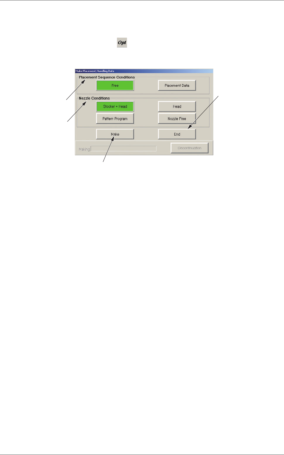
2.5 Optimization of Pattern Program
The currently opened pattern program can be optimized.
When the optimize icon (
) is pressed in the "Pattern Program" edit
window, the "Make Placement/Handling Data" dialog box opens.
[3]
[1]
[4]
[2]
Fig. 3C48 "Make Placement/Handling Data" Dialog Box
[1] "Placement Sequence Conditions" Group Box
The order of component placement for the optimization can be
specifi ed.
[Free] Button
When selected, this makes it possible to create the data that will enable
the component placement based on the production tact (priority).
Note:
When "Block Sort" is set up for the placement data, the order of
component placement based on "Block Sort" takes priority.
[Placement Data] Button
When selected, this makes it possible to create the data that will enable
the component placement in the order specifi ed in the placement data.
Note:
When "Block Sort" is set up for the placement data, the order of
component placement based on "Block Sort" takes priority.
0607-003
2.5 Optimization of Pattern Program

3-62
AKFEDT-ID
[2] "Nozzle Conditions" Group Box
The condition of the nozzle used for the optimization can be specifi ed.
[Stocker + Head] Button
When selected, this makes it possible to create the data that will enable
the production by using the head for the optimization and only the
nozzles in the nozzle stockers (housings).
The nozzle arrangement on the head is changed.
[Head] Button
When selected, this makes it possible to create the data that will
enable the production by using only the nozzles on the head for the
optimization.
[Pattern Program] Button
When selected, this makes it possible to create the data that will enable
the production by using the nozzles specifi ed in the placement head/
nozzle data in the pattern program data.
[Nozzle Free] Button
When selected, this button makes it possible to create data for PCB
production using all registered nozzles.
[3] [Make] Button
When selected, this executes the optimization.
[4] [End] Button
Press this button to exit from the optimization session without executing
the optimization or after the optimization has failed.
•
Operation Procedure
(1) Open the pattern program to be optimized.
(2) Press the (
) button.
The "Make Placement/Handling Data" dialog box opens.
(3) Specify the order of the component placement and the condition of
the nozzle used for the optimization.
(4) Press the [Make] button.
When the pattern program cannot be optimized, the contents are
displayed in the lower area of the "Make Placement/Handling Data"
dialog box. Check the contents and remove the cause. After that,
execute the optimization again.
(5) When the optimization is completed, a "Confi rmation" window
opens.
Press the [Over Write] or the [Save as...] button to save the results
of optimization.
0607-003
2.5 Optimization of Pattern Program